www.metrocount.com
Lockout
The Lockout eliminates spurious axle hits
caused by tube slap from poorly installed tubes
or slow moving vehicles, as wheels roll onto
and then off the tube.
It is important to select a lockout time that
minimises the number of spurious hits
without removing real axle hits. When a tube
spans multiple lanes, two real axle hits can
quite reasonably be only a few milliseconds
apart. The alongside table describes the
recommended lockout settings.
Lockout
Description
10ms
Multiple Lane Default
- Use this setting
for tubes that span more than one lane,
assuming ideal road quality.
20ms
Multiple Lane Special
- Use this setting
for a tube that spans more than one
lane, where road quality is poor or traffic
is slow moving.
30ms
Single Lane Default
- Use this setting
for a tube that spans one lane only,
assuming ideal road quality.
40ms
Single Lane Special
- Use this setting for
a tube that spans more than one lane,
where road quality is poor or traffic is
slow moving.
>50ms
Single Lane Special
- Use this setting for
a tube that spans one lane only, under
exceptional circumstances such as car
parks.
Lane Numbering
The lane number is used to distinguish data
collected from multiple RoadPod units at one
site. By convention, a lane number of zero (0) is
used for sites using only one RoadPod unit.
For multiple installations at a single site, adopt
a consistent lane numbering convention. For
example, number the lanes consecutively,
starting at one (1) from the north (north-south
roads) or east (east-west roads).
Count installation
To obtain short-term volume data, the
RoadPod system can also be used in several
Count Sensor Layouts. Each of the sensors can
be placed independently of each other, across
multiple lanes. Alternatively, the sensors can be
used in a split mode.
Count Sensor Layouts provide you with
basic volume information, as well as traffic
characterisation, such as gap analysis.
Each pneumatic tube should be secured using
the method described for a Classifier Sensors
Layout. Note that, this time around, equal tube
lengths is not an issue.
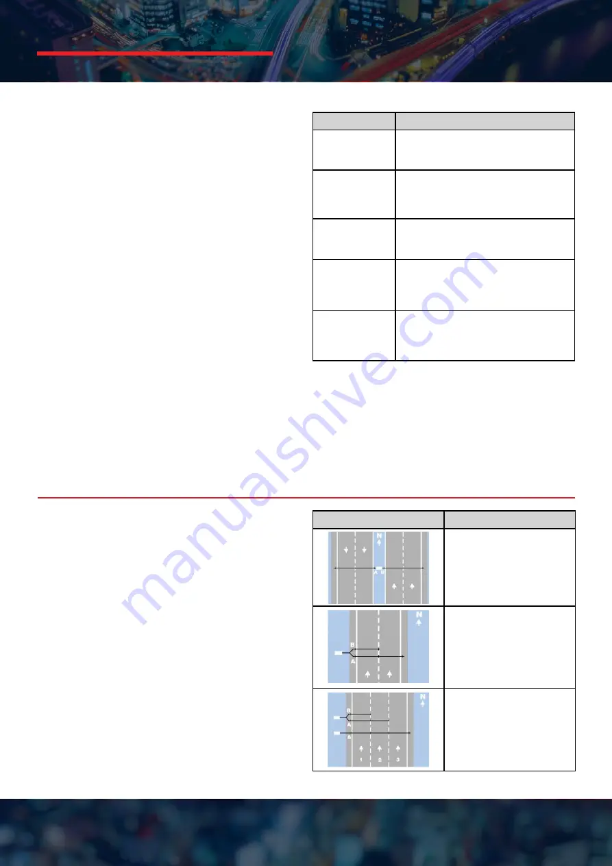
The table alongside provides some examples of
Count Sensor Layouts.
Count Sensor Layout
Description
Separate Mode
- Each
sensor is used independently
of the other.
Split Mode 1
- Used to
obtain axle-based data
across multiple lanes. MTE
handles the necessary data
manipulation.
Split Mode 2
- This example
extends the split mode
concept across multiple
lanes. MTE handles the
necessary data manipulation.
MetroCount
Traffic Data Specialists
®
Page 8


