background image


Autolab/Electronic load combination 


13 | 

P a g e


6.3


– Connections with a FRA2 module 

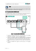
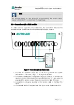
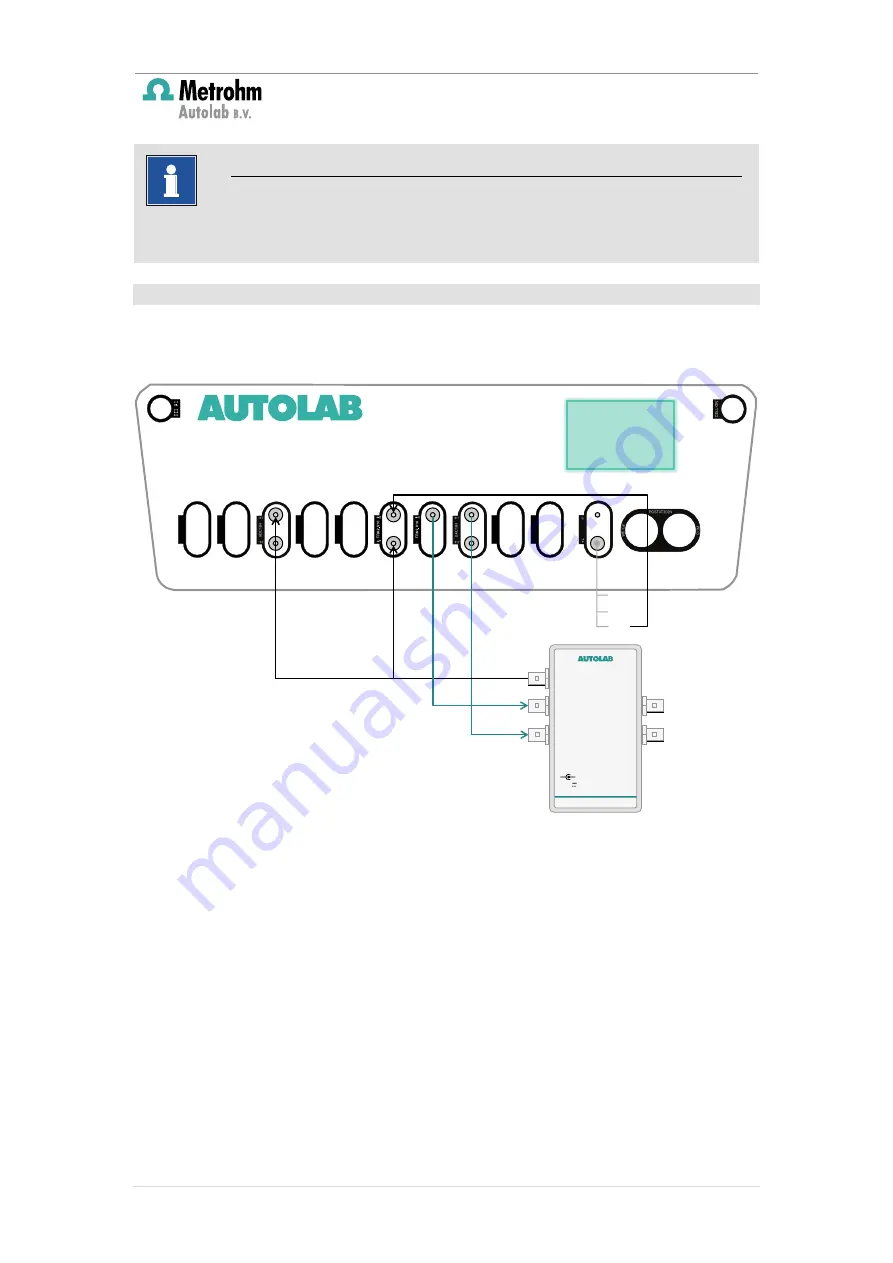
If a FRA2  module is present in the instrument, the connections between the 
Autolab and the Dynload interface should be as described in Figure 9. 


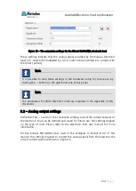
Figure 9 – Connections with the FRA2 module 

1.


Connect the DAC164 output one on the front panel of the Autolab 
(DAC164 

1) to the DAC-1 input of the Dynload interface.  

2.


Connect the Y-FRA/ADC output of the Dynload interface to the ADC164 
input one on the front panel of the Autolab (ADC164 

1) and using the 

provided BNC splitter, connect the same signal to the FRA2 

Y input.  

3.


Connect the Eout signal, provided by the monitor cable to the FRA2 

input.  

4.


Connect the FRA2 V

 output to the DSG input on the Dynload interface. 

DYNAMIC LOAD

External prog.

DAC-1

DSG

Y-FRA/ADC

I-M

15 V

+

-

Eout

Iout

Ein


Note 


For the PGSTAT204, use the Vout and Vin provided by the monitor cable 
instead of DAC164 

1 and ADC164 

1, respectively. 

Summary of Contents for Autolab

Page 1: ...Autolab Electronic Load Installation Description Picture Courtesy of Nedstack Fuel Cell Technology BV ...

Page 2: ...the dedicated DYNLOAD interface Article code LOAD INT Using the DYNLOAD interface several types of measurements are possible DC measurements at high current densities up to the maximum current allowed by the load Electrochemical impedance spectroscopy measurements at high current density up to the maximum current allowed by the load Most electronic loads can be controlled in four operation modes C...

Page 3: ...tion with the Autolab however the other modes are also available but these modes are affected by ohmic losses and are therefore not accurate Warning When the Autolab is combined with an electronic load the Autolab will only be used to control the load and measure the cell voltage The specifications of the Autolab are therefore irrelevant for this application and only the specifications of the elec...

Page 4: ...tronic load 20 8 3 1 Controlling the electronic load TDI 20 8 3 2 Controlling the electronic load Kikusui 20 9 NOVA hardware setup 21 9 1 Analog input settings 22 9 2 Analog output settings 23 10 Manual control of the electronic load DC only 24 11 Procedure control of the electronic load DC only 27 12 Recording the output from the electronic load DC only 30 13 Impedance spectroscopy measurements 3...

Page 5: ...ent 6060B Single cells small stacks 20 kHz Agilent 3300 Single cells small stacks 20 kHz Chroma 6300 Medium stacks 20 kHz Table 1 Overview of compatible electronic loads For small energy storage devices a low power electronic load is sufficient For larger devices more powerful electronic loads are required Some electronic loads require active cooling for power dissipation As a rule it is not possi...

Page 6: ...e Dynload interface see Figure 2 2 15 V power supply 3 A 2 m long BNC cable 4 A 50 Ω terminator plug 5 6 BNC to SMB adaptor plugs 6 3 SMB shielded cables 1 m 7 A BNC splitter Note A special Dynload interface version suitable for the Electronic loads supplied by the Japanese brand Kikusui is available on request see Figure 2 This version is only suitable for the Kikusui loads ...

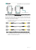
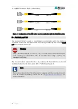
Page 7: ...ver these cables can be modified accordingly For the FRA2 module the cables must be fitted with SMB to BNC adaptors on both ends see Figure 3 Figure 3 Configuration of the SMB cables used in combination with the FRA2 module For the FRA32M module the cables must be fitted with SMB to BNC adaptors on a single end see Figure 4 DYNAMIC LOAD External prog DAC 1 DSG Y FRA ADC I M 15 V To back panel of e...

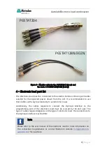
Page 8: ...The monitor cable is required for the combination with the electronic load and it must be attached to the front panel of the PGSTAT see Figure 5 Dynload FRA Y Dynl DSG FRA V E out FRA X Warning Never connect the WE CE connectors of the Autolab to the electrochemical cell when working in combination with an electronic load High currents can damage the Autolab Note The monitor cable for the PGSTAT20...

Page 9: ...k cables with very low resistivity to avoid ohmic losses Additionally the cables required to connect the Dynload interface to the programming port of the electronic load must be sourced by the end user The type of cables required depends on the type of electronic load The connections to the Dynload interface must be BNC PGSTAT204 PGSTAT128N 302N Note Please refer to the user manual of the electron...

Page 10: ...egative The software can be adjusted to account for this polarity convention 6 Connections to the Dynload interface This section describes the connections required to perform the measurements with the Autolab in combination with an electronic load The connections depend on the instrument type and configuration In the rest of this document an N series Autolab instrument is used however other instru...

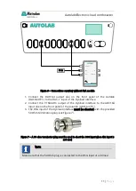
Page 11: ...ut of the Dynload interface to the ADC164 input one on the front panel of the Autolab ADC164 1 3 The DSG input of the Dynload interface must be shorted with the provided 50 Ohm termination plug see Figure 7 Figure 7 A 50 ohm terminator plug must be used to short the DSG input when this input is not used DYNAMIC LOAD External prog DAC 1 DSG Y FRA ADC I M 15 V 50 Ω Note Make sure that the 50 Ohm plu...

Page 12: ...of the Dynload interface 2 Connect the Y FRA ADC output of the Dynload interface to the ADC164 input one on the front panel of the Autolab ADC164 1 and using the provided BNC splitter connect the same signal to the FRA32M Y input 3 Connect the Eout signal provided by the monitor cable to the FRA32M X input 4 Connect the FRA32M V output to the DSG input on the Dynload interface DYNAMIC LOAD Externa...

Page 13: ...of the Dynload interface 2 Connect the Y FRA ADC output of the Dynload interface to the ADC164 input one on the front panel of the Autolab ADC164 1 and using the provided BNC splitter connect the same signal to the FRA2 Y input 3 Connect the Eout signal provided by the monitor cable to the FRA2 X input 4 Connect the FRA2 V output to the DSG input on the Dynload interface DYNAMIC LOAD External prog...

Page 14: ...butor in case of any doubts 𝐸𝐿𝑂𝐴𝐷 𝐸𝐴𝑈𝑇 𝑖𝑅 Warning The cables connecting the electronic load to the cell must have the lowest possible resistance and should be able to withstand high current densities Keep in mind that ohmic losses cannot completely be avoided Most electronic loads have a voltage reversal detection circuit which monitors the cell voltage and shuts down the load when this value beco...

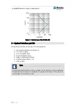
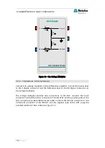
Page 15: ...e multiplier part list The Voltage Multiplier kit includes the following items 1 The Voltage Multiplier box see Figure 10 2 A red 30 cm long male banana to banana cable 3 A blue 30 cm long male banana to banana cable Note It is recommended to connect the RE and S leads from the PGSTAT as close as possible to the cell Important restriction The Voltage Multiplier reduces the input impedance of the P...

Page 16: ...or on the voltage multiplier The voltage multiplier provides two connections to the DUT Connect the S Cell connector to the WE banana connector of the PGSTAT and the positive pole of the DUT using the provided additional red cable Connect the RE Cell connector to the CE banana connector of the PGSTAT and the negative pole of the DUT using the provided additional blue cable see Figure 11 RE Pgstat ...

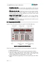
Page 17: ... B V for setup guidelines info metrohm autolab com Most electronic loads have a number of common settings which have to be considered External control ON OFF all electronic loads have a switch which activates or deactivates the external programming capability This switch must be set to ON Differential amplifier S RE GND S RE Voltage multiplier Differential amplifier S RE GND S RE Warning Connect t...

Page 18: ...ing to the experimental conditions Cell switch all electronic loads have a manual cell switch which must be set ON before the measurement starts 8 1 Programming the load TDI Figure 12 shows the overview of the front panel of the TDI RBL 488 series Figure 12 Front panel of the TDI RBL 488 series Follow these steps to ensure that the load is setup correctly for this application 1 Switch on the TDI l...

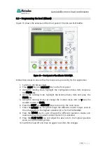
Page 19: ...rotating knob highlight the External menu item and press the ENTER key 5 Using the rotating knob set change the Control menu item to V and the LoadOn In item to HIGH 6 Press the SHIFT and SET VSET keys to return to the main menu 7 Press the RANGE key to cycle through the different current ranges and set the active range to the highest available 33 A for the PLZ164WA 8 Press the MODE key to cycle t...

Page 20: ...te at 0 A With a 10 V analog signal from the PGSTAT the load will operate at 300 A The same conversion is used for the current readout The electronic load has an analog output corresponding to the measured current The range of the current monitor analog signal is 0 10 V which corresponds to the range of 0 A to maximum current which depends on the selected current range of the electronic load The T...

Page 21: ... the range of 0 A to maximum current which depends on the selected current range of the electronic load The Kikusui PLZ164WA 150 V 33 A 165 W is an electronic load with a maximum voltage of 150 V and a maximum current of 33 A The maximum power is 165 W Operating in the 33 A current range the current monitor conversion factor will be 𝐶𝑓 33 𝐴 10 𝑉 3 3 𝐴 𝑉 With 0 V output voltage measured on the curr...

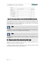
Page 22: ...ware setup click the button to close the window 9 1 Analog input settings In the ADC164 1 section the conversion settings required to measure the current from the external output of the electronic load can be defined and saved for future use The settings depend on the type of load Please refer to the electronic load user manual for more information For the Kikusui PLZ164WA load used in the example...

Page 23: ...nt of the electronic load can be defined and saved for future use The settings depend on the type of load Please refer to the electronic load user manual for more information For the Kikusui PLZ164WA load used in the examples in Section 8 3 2 of this manual the settings required to convert the analog signal from the load into the correct current value are shown in Figure 16 Note It is possible to ...

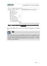
Page 24: ...fied these are defined by the electronic load 10 Manual control of the electronic load DC only Manual control of the electronic load is possible in NOVA provided that the settings are specified correctly see Section 9 To open the manual control of the electronic load select the External manual control option from the View menu see Figure 17 Note It is possible to save these settings in the Hardwar...

Page 25: ...ith an additional panel below it see Figure 18 Note The Current value shown in the Autolab control window corresponds to the current measured by Autolab Since the Autolab is not connected to the cell this value will be 0 and needs to be ignored at all times All the manual settings available in the Autolab display iR compensation current range are also irrelevant for this application ...

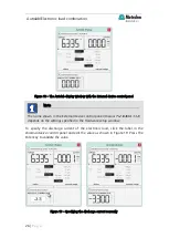
Page 26: ...nt of the electronic load click the label in the External device control panel and edit the value as shown in Figure 19 Press the Enter key to validate the value Figure 19 Specifying the discharge current manually Note The name shown in the External device control panel Kikusui PLZ164WA 33 A depends on the settings specified in the Hardware setup window ...

Page 27: ...on 9 To define the discharge current setpoint of the electronic load at any time in a NOVA procedure the Control external device command can be used To edit the settings click the button next to this command in the procedure editor see Figure 20 Figure 20 Using the Autolab control command to edit the current setpoint of the electronic load A new window called Autolab control will be displayed see ...

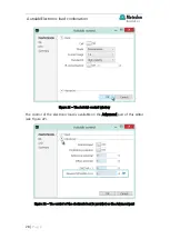
Page 28: ...nation 28 P a g e Figure 21 The Autolab control window The control of the electronic load is available on the Advanced part of this editor see Figure 22 Figure 22 The control of the electronic load is provided on the Advanced part ...

Page 29: ...d of the Autolab control window It can also be specified by sliding the provided slider in the same editor see Figure 23 Figure 23 Setting the electronic load setpoint top manually bottom using the slider Click the OK button to close the window The procedure will be updated displaying the value specified in the Autolab control window see Figure 24 ...

Page 30: ... electronic load setpoint to an Input box command 12 Recording the output from the electronic load DC only The output of the electronic load is fed back to one of the external inputs of the Autolab If the conversion settings are specified properly as indicated in Section 9 the output from the load can be converted directly and recorded by the NOVA software To sample the output of the electronic lo...

Page 31: ...otted during a measurement and will be displayed in the Autolab display window see Figure 27 Note The output signal of the electronic load can be sampled by any measurement command that uses the Signal sampler Warning The WE 1 Current WE 1 Power WE 1 Resistance and WE 1 Charge signals cannot be sampled since the WE is not connected to the cell in the application ...

Page 32: ...n be plotted and displayed in the Autolab display window when sampled Since the measurements are performed without switching the cell switch of the Autolab on a warning will be shown during validation see Figure 28 Note The value shown in the Autolab display is only visible during a measurement ...

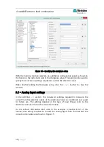
Page 33: ...ts are possible using similar settings as those defined in the Hardware setup of NOVA A dedicated command FRA measurement external is available in the Measurement Impedance group of commands To perform a frequency scan using the external electronic load drag and drop the FRA measurement external command into the procedure editor see Figure 29 Note Impedance spectroscopy measurements require the de...

Page 34: ...the FRA measurement external command to the procedure To edit the settings of the FRA measurement external command click the button next to the command in the procedure editor see Figure 29 A new window will be displayed see Figure 30 Figure 30 The FRA editor window ...

Page 35: ...unction 13 1 1 Settings for V The parameters for the V signal define the conversion factor between the output of the FRA2 FRA32M module and the input of the electronic load For this application set the Unit parameter to A and specify a multiplier see Figure 31 Figure 31 Setting the parameters for the V output The value of the multiplier depends on the type of electronic load and the settings for t...

Page 36: ... application set the name to Potential set the Unit parameter to V and specify a multiplier of 1 see Figure 32 Figure 32 Setting the parameters for the X input 13 1 3 Settings for Y The parameters for the Y signal define the conversion factor between the analog output of the electronic load and the Y input channel of the FRA2 FRA32M For this application set the name to Current set the Unit paramet...

Page 37: ...ings for Transfer function The parameters for the Transfer function define the way the transfer function is calculated and identified during a measurement For convenience sake the name and unit of the transfer function can be adjusted here as shown in Figure 34 2 The sign is used to correct the output of the load for the polarity convention as indicated in Section 5 Note The parameters for other e...

Page 38: ...RA editor window are related to the frequency scan itself This section can be used to specify the parameters for the frequency scan see Figure 35 More information is provided in the Impedance tutorial provided in the Help menu of Nova Note Make sure that the settings defined on the External section of the FRA editor are adjusted properly before editing the settings on the Frequency scan section ...

Page 39: ...Sampler section of the FRA editor window are related to the signals to sample during the impedance spectroscopy measurement and the acquisition parameters see Figure 36 Note The amplitude value is specified in absolute values Warning Make sure that that the amplitude defined in the FRA editor is smaller than the DC setpoint of the electronic load ...

Page 40: ... the linearity of the cell response Sample frequency domain if this option is active the frequency domain information will be sampled and stored for both input signals The frequency domain information consists of the calculated FFT results obtained from the measured time domain The frequency domain information can be used to evaluate the measured frequency contributions Sample DC active by default...

Page 41: ...eters see Figure 37 Figure 37 The plot settings are defined on the Plots section of the FRA editor More information is provided in the Impedance tutorial provided in the Help menu of Nova When all the parameters and settings are specified click the button to close the FRA editor The procedure editor will be updated see Figure 38 Note The available plots on the Plots section depend on the signals s...

Page 42: ...re 38 The procedure editor is updated after all the settings are specified in the FRA editor 13 5 Running a measurement Using the recommended settings specified in this Section impedance measurement can be carried out and displayed as shown in Figure 39 ...

Page 43: ...a typical impedance measurement using an external electronic load Note Metrohm Autolab can assist in setting up the experimental conditions and the procedure used to perform the measurements Contact info metrohm autolab com or your local distributor for more information ...

Page 44: ...and and the Repeat for each value command provides the backbone for a complete i V and power curve measurement as shown in Figure 40 Figure 40 Typical i V curve of a fuel cell stack 14 1 1 Running the measurement Using the Control external device and the Record signals 1 ms commands it is possible to construct a complete procedure to perform an i V measurement using the electronic load Figure 41 s...

Page 45: ...sed to walk through different current values The Calculate signal command is used to calculate the power so that it can be plotted against the discharge current For more information please refer to the NOVA user manual 14 2 Impedance spectroscopy measurement The combination of the Control external device command and the FRA measurement external command provides the backbone for a complete impedanc...

Page 46: ...DC current 9 A AC amplitude Figure 42 shows a typical Nyquist plot that can be obtained with an electronic load The measurements were obtained at 120 A and 200 A DC current with a 9 A AC amplitude The TDI RBL 488 was used for these measurements Figure 41 shows an example of a suitable procedure for this type of measurement ...

Page 47: ...orm an impedance spectroscopy measurement using an electronic load in combination with the Autolab Note Metrohm Autolab can assist in setting up the experimental conditions and the procedure used to perform the measurements Contact info metrohm autolab com or your local distributor for more information ...

Page 48: ... 6 6 Chroma 6300 60 6 6 Table 2 Overview of the DC settings to be specified in the Hardware setup for known electronic loads Load Current range A V Settings Y Settings Kikusui PLZ164WA 33 0 303 3 3 Kikusui PLZ664WA 132 0 0757 13 2 TDI RBL 488 300 0 0333 30 TDI WCL 488 1000 0 0100 100 Agilent 6060B 60 0 166 6 Agilent 3300 60 0 166 6 Chroma 6300 60 0 166 6 Table 3 Overview of the AC settings to be s...

Page 49: ...tor in case of any doubts The modification described in this document requires the following items 1 ESD safety kit see Figure 44 2 Soldering iron and solder The modification requires soldering JP2 and JP3 of the analog board of the FRA2 module Figure 44 shows a picture of the Analog board The two jumpers are highlighted Figure 44 The FRA2 Analog board JP2 and JP3 are highlighted The two jumpers n...

Page 50: ...es cabinet pdf The FRA2 module consists of 2 PCBs see Figure 45 One PCB is the digital signal generator DSG PCB and the second one is the Analog PCB Figure 45 The FRA2 consists of two PCBs the DSG on top and the Analog below To access the Analog PCB the DSG PCB must be detached To do this gently push on both sides of the board as shown in Figure 46 and Figure 47 Note It is recommended to store the...

Page 51: ...gure 46 Pressure points on the DSG PCB Figure 47 The removed DSG PCB and the Analog PCB of the FRA2 module Figure 47 shows the FRA2 module with the removed DSG PSB Locate JP2 and JP3 on the Analog PCB and close both jumpers by applying a bit a solder ...

Page 52: ...owing the instructions provided in the installation guides mentioned at the beginning of this section After modification of the FRA2 module has been modified the software needs to be adjusted The FRA2 input range is directly specified in the Hardware setup Start NOVA and open the Hardware setup Tools Hardware setup Locate the FRA offset DAC range toggle at the bottom of the Hardware setup window s...

Page 53: ...this toggle to 10 V as shown in Figure 49 Click OK to close the Hardware setup and save the modifications when prompted This modification is permanent If necessary new labels article codes CAB LABEL FRA2 V10 V and CAB LABEL FRA2 V10 XY can be ordered for the modified FRA2 module see Figure 50 Figure 50 FRA2 10 V input range labels ...

Reviews: