Autolab/Electronic load combination
50 |
P a g e
1.
For the PGSTAT128N, PGSTAT302N, PGSTAT302F and PGSTAT100N:
All modules – Insert new module in 8-series cabinet.pdf
2.
for the PGSTAT12, PGSTAT30, PGSTAT302 and PGSTAT100
All modules – Insert new module in 7-series cabinet.pdf
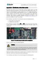
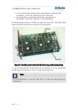
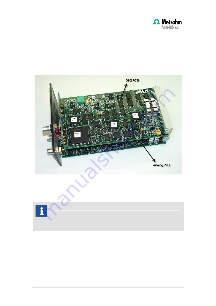
The FRA2 module consists of 2 PCBs (see Figure 45). One PCB is the digital signal
generator (DSG) PCB and the second one is the Analog PCB.
Figure 45 – The FRA2 consists of two PCBs (the DSG on top, and the Analog below)
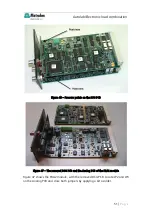
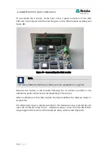
To access the Analog PCB, the DSG PCB must be detached. To do this, gently push
on both sides of the board as shown in Figure 46 and Figure 47.
Note
It is recommended to store the DSG PCB in an ESD safe bag during the
modification.

