background image

28

A

PPENDIX 

B (

CONTINUED

)

Parameter

Default

RS-232*

Light 

Pen

DTS/NIXDORF

*

NCR F

NCR S

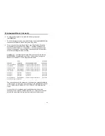
Poll Light Pen Source

a

Beeper Tone

Normal

a

a

Beep/Transmit Sequence

Before

Transmit

a

a

Communication Timeout

None

a

a

Razzberry Tone on Timeout

a

a

Three Beeps on Timeout

a

a

No Beeps on Timeout

*

a

a

Enter Power Save Mode

10 mins.

a

a

Same Symbol Rescan
Timeout:  200 msecs

a

a

Same Symbol Rescan
Timeout:  500 msecs
Programmable in 50 msec steps
(MAX 6.35 seconds)

*

a

a

Same Symbol Rescan
Timeout:  1250 msecs

a

a

Same Symbol Rescan
Timeout:  2000 msecs

a

a

Intercharacter Delay Programmable
in 1 msec steps(MAX 255 msecs)

1 msecs

10 msecs in

KBW

a

Number of Scan Buffers

1

a

a

Transmit UPC-A Check Digit

*

a

a

Transmit UPC-E Check Digit

a

a

Expand UPC-E

a

a

Convert UPC-A to EAN-13

a

Transmit Lead Zero on UPC-E

a

a

Convert EAN-8 to EAN-13

a

Transmit UPC-A Number System

*

a

a

Summary of Contents for Cubit IS6520 Series

Page 1: ...METROLOGIC INSTRUMENTS INC IS6520 MS6520 Cubit Series Omnidirectional Bar Code Scanner Installation and User s Guide ...

Page 2: ......

Page 3: ...Flórida 1821 5 Andar Fax 5511 5507 2301 São Paulo SP Brasil Email info br metrologic com CEP 04571 090 Asia Metrologic Asia Pte Ltd Tel 65 842 7155 31 Kaki Bukit Road 3 Fax 65 842 7166 05 08 Techlink Email info sg metrologic com Singapore 417818 China Metro Technologies Co Ltd Tel 86 512 2572511 221 Xing Hai Street Fax 86 512 2571517 Suzhou Industrial Park Email info cn metrologic com Suzhou China...

Page 4: ...iii Printed in USA March 2000 ...

Page 5: ...onnecting the PowerLink Cables from the Scanner 7 Scanner Parts 8 Mounting Holes 9 Audible Indicators 10 Failure Modes 11 Visual Indicators 12 Programming Modes 13 Labels 17 Maintenance 17 Optimal Low and Close Depth of Field 18 Optimal High and Normal Depth of Field 19 Far Depth of Field 20 Troubleshooting Guide 21 Appendix A Design Specifications 25 Appendix B Default Settings 27 ...

Page 6: ...v TABLE OF CONTENTS Appendix C Scanner Pinout Connections 32 Cable Connector Configurations 32 Appendix D Warranty and Disclaimer 35 Appendix E Notices 37 Appendix F Patents 39 Index 40 ...

Page 7: ... Printer Note Leave page blank ...

Page 8: ...werLink quick disconnect cables The modular design of Cubit allows the unit to be tailored to meet the needs of a specific application As a retail scanner the MS6520 s user friendly mounting bracket bolts securely to the countertop or wall for fixed mount scanning Cubit s small size and aggressive scan pattern make it ideal for convenience sporting goods apparel and toy hobby stores Furthermore Cu...

Page 9: ...coiled cord long strain relief xxx specifies connection to the host Keyboard Wedge Powerlink and Adapter Cable MLPN 54 54002 Powerlink cable with a 5 pin DIN female connector and a 6 pin mini Din male connector and an adapter cable with a 5 pin DIN male connector and a 6 pin mini DIN female connector IS650 47 MS6520 47 only Mounting Hardware 3 screws 3 mm are included for mounting purposes Install...

Page 10: ...e the AC input requirements of the power supply match the AC outlet 4 When the IS6520 is ready to scan the green LED will turn on the red LED will flash and the scanner will beep once 5 Place a bar code in front of the scanning window The scanner will beep once and flash the red LED if the bar code was successfully decoded NOTE Cubit is shipped from the factory programmed with default settings Ref...

Page 11: ...rn on the host system Note Plugging the scanner into a port on the host system does not guarantee that scanned information will be communicated properly to the host system The scanner is shipped from the factory programmed with default settings Please refer to the MetroSelect Programming Manual MLPN 2407 for instructions on changing the scanner s configuration In addition please check that the sca...

Page 12: ...cording to the termination required connect the appropriate end of the adapter cable to the PowerLink cable leaving the necessary termination exposed for connecting to the keyboard and the keyboard port on the PC Refer to Appendix C page 31 for pin assignments 7 Connect to the PowerLink cable to the keyboard and the keyboard port on the PC 8 Power up the PC Manufacturer s Recommendation Metrologic...

Page 13: ...6 To maintain compliance with standard CSA C22 2 No 950 UL 1950 and norm EN 60950 the power source should meet applicable performance requirements for a limited power source ...

Page 14: ...ower supply has been disconnected from the PowerLink cable 1 Locate the small pin hole on the back of the scanner 2 Bend an ordinary paperclip into the shape shown above 3 Insert the paperclip or other small metallic pin into the small pin hole 4 You will here a faint click Pull gently on the strain relief of the PowerLink cable and it will slide out of the scanner Ž Œ ...

Page 15: ...sful read of a bar code the red LED will turn on After communication to the host is complete the red LED will turn off The LEDs are also used as diagnostic indicators and mode indicators C Output Window Laser light emits form this aperture D Powerlink Cable The IS6520 MS6520 scanner has a 10 pin modular jack The 10 pin modular plug on the PowerLink cable connects into the IS6520 MS6520 A D B C ...

Page 16: ...nner The following diagram shows the exact location of each mounting hole The mounting holes are 6 millimeters deep and are threaded for use with 3 millimeter screws Caution Using a screw that is longer than 6 millimeters can potentially damage the scanner 62 mm 2 4 41 mm 1 6 20 mm 0 8 0 mm 0 0 mm 0 20 mm 0 8 82 mm 3 2 ...

Page 17: ...s not flash then the bar code has not been successfully read Razzberry Tone This tone is a failure indicator Refer to Failure Modes page 10 Three Beeps During Operation During operation of the scanner the red LED will flash while the scanner simultaneously beeps three times while going into programming mode The red LED will continue to flash until the unit exits program mode Upon exiting program m...

Page 18: ...or failure Return the unit for repair at an authorized service center Continuous Razzberry Tone with Both LEDs Off If upon power up the scanner emits a continuous razzberry tone then the scanner has an electronic failure Return the unit for repair at an authorized service center Three Beeps On Power Up If the scanner beeps 3 times on power up then the non volatile memory that holds the scanner con...

Page 19: ...ed Flash When the scanner successfully reads a bar code the red LED will flash and the scanner will beep once If the red LED does not flash or the scanner does not beep once then the bar code has not been successfully read Steady Green and Steady Red After a successful scan the scanner transmits the data to the host device Some communication modes require that the host inform the scanner when data...

Page 20: ... values of the bar codes located in the MetroSelect Configuration Guide MLPN 2407 How does Serial Programming work 1 Each command sent to the scanner is the ASCII representation of each numeral in the configuration bar code The entire numeric string is framed with an ASCII stx and an ASCII etx EXAMPLE 1 Command for Disabling Codabar Command stx 100104 etx String Sent to Scanner 02h 31h 30h 30h 31h...

Page 21: ... Mode stx 999999 etx 02h 39h 39h 39h 39h 39h 39h 03h ack or 06h Load Defaults stx 999998 etx 02h 39h 39h 39h 39h 39h 38h 03h ack or 06h Disable Code 128 stx 100113 etx 02h 31h 30h 30h 31h 31h 33h 03h ack or 06h Alternate Tone 1 stx 318565 etx 02h 33h 31h 38h 35h 36h 35h 03h ack or 06h Prog Prefix 1 stx 903500 etx 02h 39h 30h 33h 35h 30h 30h 03h ack or 06h Code Byte 0 stx 0 etx 02h 30h 03h ack or 0...

Page 22: ...faults stx 999998 etx 02h 39h 39h 39h 39h 39h 39h 03h ack or 06h 19200 Baud Rate stx 415870 etx 02h 34h 31h 35h 38h 37h 30h 03h ack or 06h Exit Program Mode stx 999999 etx 02h 39h 39h 39h 39h 39h 39h 03h ack or 06h The scanner will emit a long beep This example illustrates 2 important points First if an invalid command is sent from the host the scanner responds with a nak and the end user must sta...

Page 23: ...16 ...

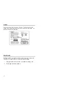
Page 24: ...al number CE and caution information The following is an example of this label MAINTENANCE Smudges and dirt can interfere with the proper scanning of a bar code Therefore the output window will need occasional cleaning 1 Spray glass cleaner onto lint free non abrasive cleaning cloth 2 Gently wipe the scanner window ...

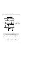
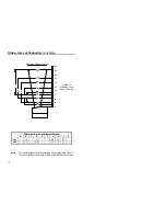
Page 25: ...5 17 25 33 53 mils 5 7 6 8 10 13 21 Note The same depth of field is achieved when programming Cubit for either Optimal Low Depth of Field or Close Depth of Field 0 25 50 75 100 125 150 175 200 250 225 B D G H J 123 45 49 73 82 95 105 40 DISTANCE SCANNER FACE TO BAR CODE mm WIDTH OF SCAN FIELD mm ...

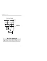
Page 26: ... 17 25 33 53 mils 5 7 6 8 10 13 21 Note The same depth of field is achieved when programming Cubit for either Optimal High Depth of Field or Normal Depth of Field 0 25 50 75 100 125 150 175 200 250 225 DISTANCE SCANNER FACE TO BAR CODE mm D G H J B 123 58 68 73 82 95 105 45 49 WIDTH OF SCAN FIELD mm ...

Page 27: ...mum Bar Code Element Width A B C D E F G H J K mm 15 17 25 33 53 mils 5 7 6 8 10 13 21 0 25 50 75 100 125 150 175 200 250 225 DISTANCE SCANNER FACE TO BAR CODE mm D G H J B 123 77 82 91 95 105 114 49 73 45 WIDTH OF SCAN FIELD mm ...

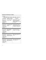
Page 28: ...nner front host Some host system s cannot supply enough current to power Omni Quest Use the power supply included with the scanner 3 beeps on power up Non volatile RAM failure Contact a Metrologic Representative if the unit will not hold the programmed configuration Continuous razz tone on power up RAM or ROM failure Contact a Metrologic Representative if the unit will not function Razz tone and g...

Page 29: ...ength and bar code being scanned does not satisfy the programmed criteria Verify that the bar code that is being scanned falls into the criteria Typical of Non UPC EAN codes The scanner defaults to a minimum of 4 character bar code The unit scans a bar code but locks up after the first scan red LED stays on The scanner is configured to support some form of host handshaking but is not receiving the...

Page 30: ...is out of tolerance Check print mode The type of printer could be the problem Change print settings ie change to econo mode or high speed Scanner beeps at some bar codes and NOT for others of the same bar code symbology The bar code may have been printed incorrectly Check if it is a check digit character or border problem Scanner beeps at some bar codes and NOT for others of the same bar code symb...

Page 31: ...stops bits and parity of the scanner and the communication port match and the program is looking for RS 232 data Powers up OK and scans OK but does not communicate properly to the host Com port not operating properly Check to make sure that the baud rate data bits stops bits and parity of the scanner and the communication port match and the program is looking for RS 232 data The host is receiving ...

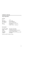
Page 32: ... Autodiscriminates all standard bar codes for other symbologies call Metrologic System Interfaces RS 232 Light Pen Emulation Keyboard Wedge Stand Alone Keyboard Print Contrast 35 minimum reflectance difference Roll Pitch Yaw 360 60 60 Indicators Green laser on ready to scan Red good read decoding Beeper Operation 7 tones or no beep Mechanical Length 102 mm 4 0 Width 83 mm 3 25 Height front edge 70...

Page 33: ...s A Laser Class CDRH Class IIa EN 60825 1 1994 A11 1996 CLASS 1 Environmental Operating Temperature 20 C to 40 C 4 F to 104 F Storage Temperature 40 C to 60 C 40 F to 140 F Humidity 5 to 95 relative humidity non condensing Light Levels Up to 4840 Lux 450 footcandles Contaminants Sealed to resist airborne particulate contaminants Ventilation None required Specifications subject to change without no...

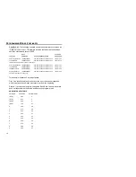
Page 34: ... If the communication supports a parameter listed in the charts on the following pages a check mark will appear Parameter Default RS 232 Light Pen UPC EAN a a Code 128 a a Code 93 a a Codabar a a Interleaved 2 of 5 ITF a a MOD 10 Check on ITF a a Code 11 a a Code 39 a a Full ASCII Code 39 a a MOD 43 Check on Code 39 a a MSI Plessey a a MSI Plessey 10 10 Check Digit a a MSI Plessey MOD 10 Check Dig...

Page 35: ...e Symbol Rescan Timeout 200 msecs a a Same Symbol Rescan Timeout 500 msecs Programmable in 50 msec steps MAX 6 35 seconds a a Same Symbol Rescan Timeout 1250 msecs a a Same Symbol Rescan Timeout 2000 msecs a a Intercharacter Delay Programmable in 1 msec steps MAX 255 msecs 1 msecs 10 msecs in KBW a Number of Scan Buffers 1 a a Transmit UPC A Check Digit a a Transmit UPC E Check Digit a a Expand UP...

Page 36: ... Stop Start Characters a Transmit Mod 10 ITF a Transmit MSI Plessey Check Characters a Parity Space a Baud Rate 9600 a 8 Data Bits a 7 Data Bits a Transmit Sanyo ID Characters a Nixdorf ID a LRC Enabled a UPC Prefix a UPC Suffix a Transmit AIM ID Characters a STX Prefix a ETX Suffix a Carriage Return a Line Feed a Tab Prefix a Tab Suffix a DE Disable Command a FL Laser Enable Command a DTR Handsha...

Page 37: ...30 Character RTS CTS a ...

Page 38: ... Find Supplement Programmable in 100 msec steps MAX 800 msec a a Coupon Code 128 a as code 39 Programmable Code Lengths 7 aval a a Programmable Prefix Characters 10 avail a Suffix Characters a Prefixes for individual Code Types Editing a a Inter Scan Code Delay Programmable 100 msec steps 800 msec Function Control Key Support Minimum Element Width Programmable in 5 6 µsec steps 1 msec a Depth of F...

Page 39: ... 4 RTS Output 5 PC Clock 5 CTS Input 6 KB Clock 6 DTR Input LTPN Source 7 PC 5V 7 Reserved 8 KB Data 8 LTPN Data 9 5VDC 9 5VDC 10 Shield Ground 10 Shield Ground Cable Connector Configurations Standard PowerLink cable MLPN 53000 or 54000 9 pin D type female connector to the PC Pin Function 1 Shield Ground 2 RS 232 Transmit Output 3 RS 232 Receive Input 4 DTR Input 5 Power Signal Ground 6 Light Pen ...

Page 40: ... exposed for connecting to the keyboard and the keyboard port on the PC The pin assignments are as follows PowerLink Cable Adapter Cable 5 pin Female DIN 5 pin Male DIN Pin Function Pin Function 1 Keyboard Clock 1 PC Clock 2 Keyboard Data 2 PC Data 3 No Connect 3 No Connect 4 Power Ground 4 Power Ground 5 5 Volts DC 5 5 Volts DC 6 pin Male Mini DIN 6 pin Female Mini DIN Pin Function Pin Function 1...

Page 41: ...34 6 No Connect 6 No Connect ...

Page 42: ...ited warranty does not extend to any Product which in the sole judgement of Metrologic has been subjected to abuse misuse neglect improper installation or accident nor any damage due to use or misuse produced from integration of the Product into any mechanical electrical or computer system The warranty is void if the case of Product is opened by anyone other than Metrologic s repair department or ...

Page 43: ...36 FAX 856 228 6673 ...

Page 44: ...tion L emploi de commandes réglages ou procédés autres que ceux décrits ici peut entraîner de graves irradiations Le client ne doit en aucun cas essayer d entretenir lui même le scanner ou le laser Ne regardez jamais directement le rayon laser même si vous croyez que le scanner est inactif N ouvrez jamais le scanner pour regarder dans l appareil Ce faisant vous vous exposez à une rayonnement laser...

Page 45: ... im Wohnbereich Funkstörungen verursachen in diesem fall kann vom Betrieber verlangt werden angemessene Maßnahmen durchführen Standard Europeo Attenzione Questo e un prodotto di classe A Se usato in vicinanza di residenze private potrebbe causare interferenze radio che potrebbero richiedere all utilizzatore opportune misure Attention Ce produit est de classe A Dans un environnement domestique ce p...

Page 46: ...62 628 5 280 162 5 280 164 5 304 788 5 321 246 5 324 924 5 396 053 5 396 055 5 408 081 5 410 139 5 436 440 5 449 891 5 468 949 5 479 000 5 532 469 5 545 889 No license right or sublicense is granted either expressly or by implication estoppel or otherwise under any METROLOGIC or third party intellectual property rights whether or not such third party rights are licensed to METROLOGIC including any...

Page 47: ... D DC transformer 25 Decode capability 24 Default settings 26 27 28 29 Depth of field 17 18 19 24 29 Design specifications 24 Disclaimer 32 E Electrical 25 F Failure indicator s 10 Failure modes 10 11 G Green LED 12 20 H Host 3 5 7 12 21 23 30 I Indicators 10 11 12 24 audible 10 LED 8 10 11 12 20 21 Visual 12 Input voltage 25 Installation 5 9 Interfaces iv 20 21 22 24 K Keyboard wedge 2 3 30 31 L ...

Page 48: ...4 R Razzberry tone 10 11 12 27 Red LED 10 12 21 Repair 11 RMA 32 RS 232 23 24 26 27 28 29 S Scan lines 24 Scan pattern 24 Scan speed 24 Service 3 11 32 Specifications 24 25 System interfaces 24 T Termination 6 24 Tones 10 11 24 Transformers 25 Troubleshooting 20 21 22 23 V Ventilation 25 Visual 12 Voltage 25 W Warranty 20 32 Weight 24 Window 8 16 ...

Reviews: