3-14
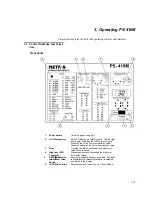
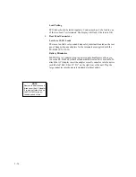
the switch must correspond to the type of patient
monitor in use.
7. Blood Pressure
Slide
Switch
(µV/V/mmHg)
Sets the sensitivity to match the input sensitivity of
the patient monitor (either 5 or 40
)
V/V/mmHg).
The waveform is selected and stored in the display.
8. Temperature Slide
Switch
Sets the temperature to be used.
9. Lead Test
Terminals
For testing ECG leads. Connect each end of the
lead to one of the two Lead Test Terminals. The
LCD display will flash if the lead is OK.
Rear Panel
10. Low level ECG
Connectors
10 AHA color-coded 4mm safety terminals. Snap-
to-banana adapters for the terminals are supplied
with the PS-416M.
11. Battery
Eliminator
Micro jack for connecting the 9V plug-in power
supply transformer for use in operating the unit
from any standard electrical outlet.
3.2 Use
1.
Power.
The power switch is the slide-switch situated at the bottom
right-hand corner of the panel. The instrument should be switched off
when not in use, to save the battery. A flashing display indicates low
battery power.
2.
Battery Replacement
The battery is situated in the base of the instru-
ment. Use a 9 volt alkaline battery (Duracell
®
MN1604 or equivalent).
3.
Top Panel Controls and Connectors
Display and Keyboard
The PS-416M has a two-digit display. To the left of the LCD display is a
listing of available waveforms and two-digit codes. Access a waveform
by displaying its corresponding two-digit code. Use the two keys below
the LCD display to enter units and tens (the right key is for units; the left
is for tens). Pressing the top of the keys increases the values, while
pressing the bottom of the keys decreases the values. The selected wave-
form is stored by pressing
Enter
. Repeat the above procedure if you de-
NOTE
Use only METRON’s AC
Adapter plug-in power sup-
ply transformer supplied with
the unit.
NOTE
Do not use mercury, air or
carbon-zinc batteries.
Summary of Contents for PS-416M
Page 1: ...1 1 PS 416M User Service Manual PATIENT SIMULATOR...
Page 4: ...1 4 This page intentionally left blank...
Page 6: ...1 6 This page intentionally left blank...
Page 10: ...1 10 This page intentionally left blank...
Page 12: ...2 12 This page intentionally left blank...
Page 20: ...4 20 This page intentionally left blank...
Page 28: ...5 28 This page intentionally left blank...
Page 29: ...5 29 Component Location...
Page 30: ...5 30 Schematic Diagram Part 1...
Page 31: ...5 31 Schematic Diagram Part 2...
Page 32: ...5 32 This page intentionally left blank...
Page 34: ...5 34 This page intentionally left blank...
Page 36: ...5 36...


