DL2
23
6.2.5 IN6TC - six channel mV type input module
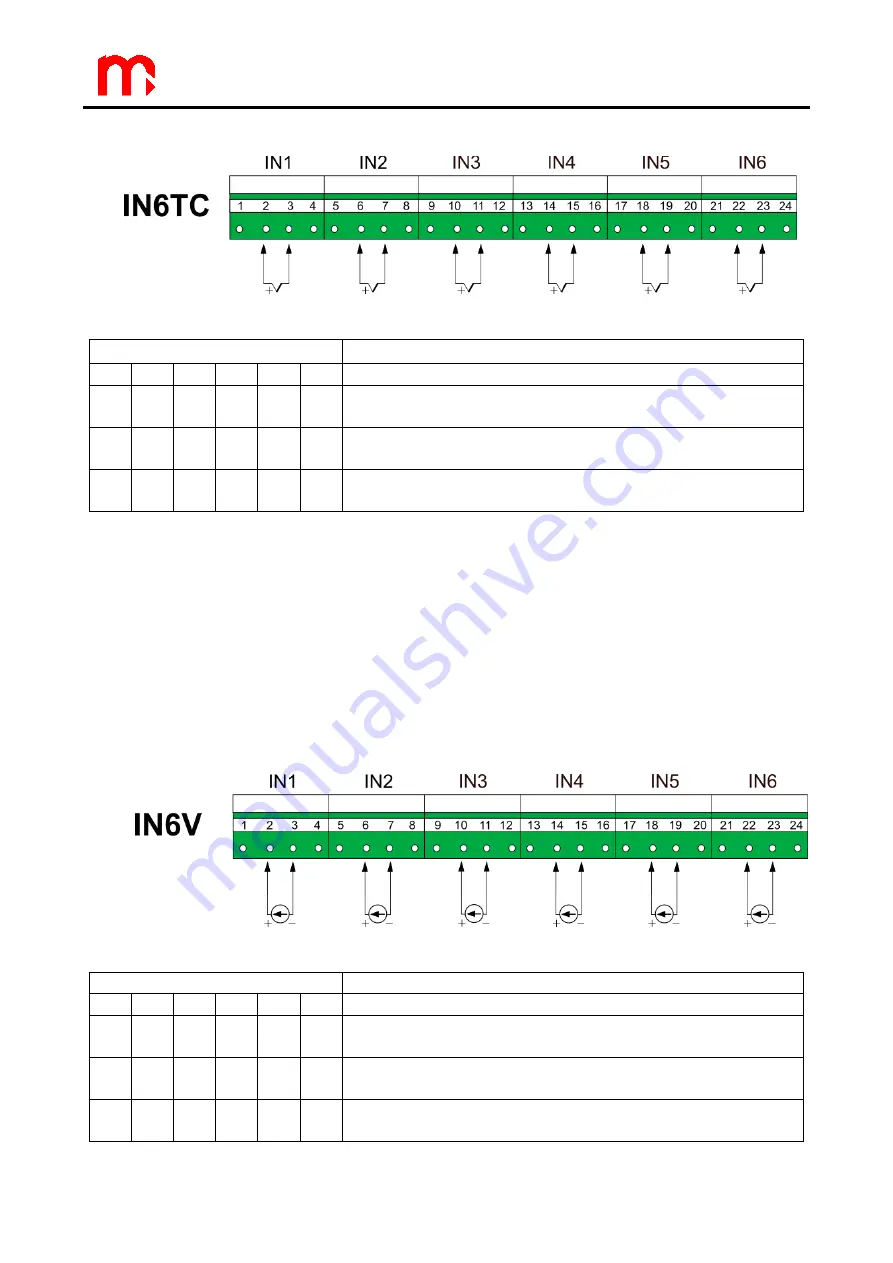
Fig. 6.7 Thermocouple wiring to IN6TC module diagram.
Terminal No
Description
1
5
9
13
17
21 Not used
2
6
10
14
18
22 mV+
Voltage signal input (+)
3
7
11
15
19
23 mV-
Voltage signal input (-)
4
8
12
16
20
24 GND A
Signal ground
Notes:
If screened cable is used to connect sensor, then GND A terminal may be used to
connect the screen. But it is more recommended to connect screen to functional ground or
e.g. metal cabinet ground (PE).
For precision temperature measurements the proper cold junction temperature
measurement have to be considered. The device during typical operation heats up about
10
°C, what has influence on the device terminals temperature. It should be considered to
move the wiring compensation cables to extra terminals in the cabinet with stable
temperature. The cold junction temperature should be measured with external temperature
sensor (e.g. Pt100) at the external terminals then.
6.2.6 IN6V
– six channel voltage type input module
Fig. 6.8 Wiring diagram of transducers to IN6V module.
Terminal No
Description
1
5
9
13
17
21 Not used
2
6
10
14
18
22 V+
Voltage signal input (+)
3
7
11
15
19
23 V-
Voltage signal input (-)
4
8
12
16
20
24 GND A
Signal ground
Summary of Contents for DL2
Page 47: ...DL2 47 Notes ...
Page 48: ...DL2 48 Notes ...


