13 Electrical installation
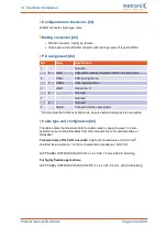
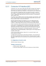
Connection notes [X6]
Connect the inner and outer cable shield with the greatest possible surface area to the
back panel of the control cabinet by way of suitable EMC terminals. The unshielded cable
end should not be longer than 80 mm.
An existing holding brake in the motor must be connected to the terminals BR+ and BR-.
Please note the maximum output current that is provided by the servo drive.
Dangerous electrical voltage!
The signals for the temperature sensor "MT-" and "MT+" at the motor connector [X6]
must be connected to protective extra-low voltage (PELV) on the motor side and they
must be insulated against the motor phases.
Risk of injury
The brake output of the servo drive (BR+, BR-) must not be used as the sole stop
element in safety-oriented applications.
Risk of destruction due to the mix-up of connectors
The servo drive may be irreparably damaged if the connectors for the motor [X6] and
supply [X9] are mixed up.
Product manual BL 4000-C
Page 243 of 298

