6 Applications
6.1.3
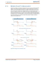
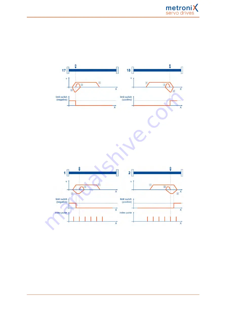
Methods 17 and 18: positive and negative limit switch
If these methods are used, the drive moves in the positive direction (18) or negative
direction (17) at search speed until it reaches the limit switch. Then, the drive moves back
at crawl speed and tries to find the exact position of the limit switch. The home position
refers to the falling edge of the limit switch.
Figure 34: Homing run to the limit switch
6.1.4
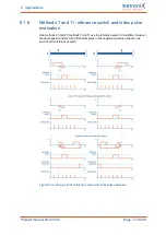
Methods 1 and 2: positive and negative limit switch
with index pulse evaluation
Like in the case of the previous method, the system tries to find the limit switch. However,
in this case, the home position refers to the first index pulse of the angle encoder in the
negative (1) or positive (2) direction as seen from the limit switch.
Figure 35: Homing run to the limit switch with index pulse evaluation
Product manual BL 4000-C
Page 75 of 298

