7
TROUBLE SHOOTING
Mechanical/electrical defects
1. A change in the valve position setpoint does not affect the
position of the actuator
supply pressure too low
spool valve sticks
tubes between controller and actuator are incorrect, see
Fig. 7
actuator and/or valve jammed
signal wires incorrectly connected, no value on display
circuit board is defective
calibration has not been carried out (
a
or
M
)
ND800PA is either in
M
or
o
mode
prestage is defective
position sensor is defective
2. The actuator goes to the final position with a small change of
input signal
tubes between controller and actuator are incorrect, see
Fig. 7
the parameter settings
FA
and
rot
are incorrectly selected.
See Figs. 7 and 10
3. Inaccurate positioning
spool valve dirty
dirt in the permanent magnet air gap
actuator too small
supply pressure too low
pressure sensor is defective
d
and
b
parameters in the
d
mode do not comply with
recommendations shown in Fig. 7
g
parameter is too small, perform
a
/
M
calibration acc. to Section 4.2
4. Overshooting or positioning too slow
g
is too high or too low, see Fig. 7
spool valve dirty
supply air tube too small or supply air filter dirty
valve sticks
check leakages in tubes between controller and actuator
check leakages in mechanical stop screws
5.
Err
is shown during calibration
position sensor is out of range, see Section 5.4
mechanical actuator travel exceeds position sensor linear
travel, i.e. 110°. If it fails in fully closed position, turn the spiral
(117) counterclockwise in 5° steps. If it fails in the fully open
position, turn the spiral (117) clockwise in 5° steps.
the parameter settings
PFA
and
rot
are incorrectly se-
lected, see Section 4.3 and Fig. 7
the actuator did not move or was stuck during calibration
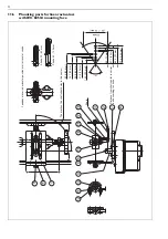
ND800PA/actuator mounting is incorrect, see Figs. 4, 5,
15 and Sections 10.2-10.6
spool valve sticks
prestage is defective
PDM trouble shooting is explained in the ND800PA User’s Guide.
8
TOOLS
No special tools needed.
9
ORDERING SPARE PARTS
Spare parts are delivered as modules. Available modules are shown
in Sections 11.1 and 11.2.
When ordering spare parts, always include the following information:
controller type designation and serial number from the ID
plate
code of this manual, part number, part name and quantity
required
When ordering the circuit board, serial number of the
position sensor
17

