background image

10

ND800/K00 (WITH LIMIT SWITCHES)

10.1

Introduction

10.1.1

General description

ND800 can be equipped with limit switches. ND800/K00 has
2 microswitches.

Limit switches are used for electrical position indication of the valves
and other devices.

The switching points can be chosen freely.

10.1.2

Markings

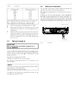
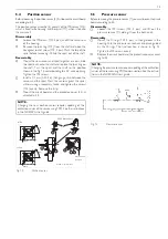
The limit switch is provided with an identification plate sticker, see
Fig. 20. Identification plate markings from top to bottom are:

Type designation
Electrical values
Enclosure class
Temperature range
Conduit entry
Serial number

The type designation is described in Chapter 13.

10.1.3

Technical specifications

10.1.3.1 ND800/K00

Microswitch type:

OMRON D2VW-5

(05)

OMRON D2VW-01

(06)

(gold plated contacts)

Protection class IP67

Resistive load:

3A: 250 V AC

 (05)

5A: 30 V DC
0.4A: 125 V DC

100 mA: 30 V DC/125 V AC (06)

Switch accuracy:

< 2°

Number of switches: 2

Protection class
of cover:

IP65 (DIN 40050, IEC 529)

Conduit entry:

PG 13.5 
1/2 NPT  = -L
M20x1.5 = -I
R 1/2  =

-NJ

Ambient temperature: -20 - +80 °C (-4 - +176 °F)

Weight:

Approx. 0.8 kg (1.8 lbs) (limit switches only)

Materials:
Body:

Aluminium alloy, epoxy-coated

Internal parts:

Stainless steel and plastic

Sealing:

Nitrile and neoprene rubber

10.1.4

Safety precautions

CAUTION:
Do not exceed the limit switch performance limitations!

Exceeding the limitations marked on the limit switch may
cause damage to the limit switch, actuator and valve. Damage
or personal injury may result.

CAUTION:
Observe caution with the live parts of the limit switch!

The limit switches are fed with a voltage that, depending on
the system, may be lethal.
Do not touch any uncovered parts of the wires. Always
disconnect the wires before dismantling the limit switch.

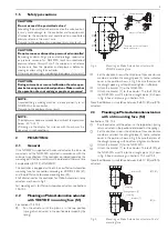
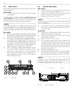
2 micro-
switches

2 cams

terminal

earth
connection

PG 13.5

Fig. 17. 

ND800/K00 layout

Fig. 18. 

Identification plate

18

Summary of Contents for ND800PA

Page 1: ...VALVECONTROLLER ND800PA Rev 1 0 Installation Maintenance and Operating Instructions 7 ND 72 en 4 2001 ...

Page 2: ...ty precautions 18 10 2 Installing ND800 K00 on a valve controller 19 10 3 Electrical connections 19 10 4 Adjustment 19 10 5 Removal of the limit switch ND800 K00 for accessing the valve controller 19 10 6 Circuit diagrams 19 10 7 Maintenance 19 10 8 Ordering spare parts 19 11 DRAWINGS AND PARTS LISTS 20 11 1 Exploded view and parts list 20 11 2 Mounting parts for B1C B1J 6 20 actuators 21 11 3 Mou...

Page 3: ...and rotates the feedback shaft A position sensor a measures the rotation for the µC Using a control algorithm the microcontroller adjusts the pilot current until a new position of the actuator proportional to the input signal is reached In the steady state the spool valve SV and prestage PR valves are closed 1 3 Markings The valve controller is equipped with an identification plate sticker Fig 2 I...

Page 4: ... 0 default Valve Type Selection TYP rot rotary valve default lin linear valve Setpoint Cut off CLOSE CLO 0 100 2 default Setpoint Cut off OPEN CHI 0 100 100 default Lower Limit Valve Position RLO 0 100 0 default Upper Limit Valve Position RHI 0 100 100 default Profibus slave address ADR 0 126 default 126 Electrical connections Input signal Profibus PA according to IEC 61158 2 Approvals Temp 75 C 6...

Page 5: ...ler for Metso Automation rotary actuators are shown in Fig 4 For mounting parts for Metso Automation actuators see Sections 10 2 10 6 2 2 MountingonMetsoAutomationactuators with VDI VDE mounting face S1 See Sections 10 2 10 4 Run the actuator until the piston is in the top position spring return actuators in the position determined by the spring Set the direction arrow in the direction of the valv...

Page 6: ...o that the measured distance is maintained betweenthe centre of the feedback lever shaft and the actuator pin pre meas ured mark on the feedback lever Note the controller must still conform to the specifications in previous steps Tighten all the mounting bolts and then re check that the controller complies with previous steps Check that the actuator pin does not touch the controller case through o...

Page 7: ...y cause faulty operation of the controller Sealing tape is not recommended Ensure the cleaniness of the air piping The supply air must be clean dry and oil free instrument air e g according to standard ISA S7 3 81 2 6 Electrical connections The bus cable is led through a PG13 5 cable gland Connect the conductors to the terminal strip according to Fig 6 Reverse polarity protection permits connectio...

Page 8: ...valves 2 Self opening Setting PFA OPE ROT cC lose valve to lockwise A0 acc to valve type cLo 2 c c C1 C2 S C1 C2 S C1 C2 S C1 C2 S C1 C2 S After self tuning the default parameters are as follows Gain 1 0 for enhanced control use Gain 1 2 d 0 0 for double acting actuators factory set d 1 0 for single acting actuators factory set b 1 0 In order to achieve symmetrical operation always use filter regu...

Page 9: ... the valve and does not respond to incoming signal Accept the selected mode by pressing the r key which returns you automatically to the setting state Move to the next setting by pressing the key g starts to flash The positioner gain required for different size of actuators is set with the g parameter g is set automatically by self tuning procedure during a M calibration Pressing the r key allows ...

Page 10: ... 5 s 5 s FACTORY 90 PREVIOUS SETTING 5 s Analog output block output signal KEYSTROKES Escape 1 s Operation state Setting state Fig 10 Keyboard operations 10 ...

Page 11: ...ow the ND800PA assumes that the maximum valve opening is the latest calibrated value The factory setting is 90 Drive the valve into the desired maximum opening posi tion 100 with the and keys and press the r key A self tuning procedure is performed If an error message Err appears on the display see Chapter 7 Press the and keys simultaneously to return to the operation state Now the valve controlle...

Page 12: ...nd functions in Fig 10 α0 setting dead angle A0 The α0 setting is made for Metso Automation segment and ball valves This setting takes into account the dead angle α0 of the ball valves The entire signal range is then used for effective valve opening 90 α0 Figure 12 and Table 3 Use 0 as the dead angle for the valves not mentioned in Table 3 After selecting A0 on the display press the r key and the ...

Page 13: ...value of 100 Profibus slave address Adr When Adr appears on the display press r key and the current value appears on the display The default is 126 Now modify this value to desired number and press r key to return the setting state see Fig 10 for instructions When all the control valve related parameters are cor rectly set return to operation state by pressing the and key simultaneously for a shor...

Page 14: ...unit and the prestage unit have an even surface connection before tightening the screws 5 3 Circuit board pack Disassembly Loosen the M8 screw 66 and turn the position indica tor 65 outwards from the feedback shaft Unplug all wire connectors from the circuit board 5 and the signal wires from the terminal block 35 Remove the M3 screws 111 5 pcs NOTE Ground yourself on the body of the device before ...

Page 15: ... and tighten the screws 116 evenly Remove the strip Mount the circuit board and the protective cover 46 as directed in 5 3 NOTE Changing the new position sensor requires updating of the calibration values of the sensor using PDM See the instructions in the ND800PA User s guide 5 5 Pressure sensor Before removing the pressure sensor 7 youmust loosenthe circuit board according to 5 3 Disassembly Loo...

Page 16: ...matic prestage valve 2 VA2 control failure Check wires and connectors or change circuit board Resistanceofthecoilisapprox 100Ω measuredfromtheprestageconnectors E51 Position feedback ADC low limit failure Check the mounting of controller the mark on the shaft must stay in the right sector see Fig 4 Check wires connector and position sensor rotation range or change circuit board Rotate the position...

Page 17: ...too low see Fig 7 spool valve dirty supply air tube too small or supply air filter dirty valve sticks check leakages in tubes between controller and actuator check leakages in mechanical stop screws 5 Err is shown during calibration position sensor is out of range see Section 5 4 mechanical actuator travel exceeds position sensor linear travel i e 110 If it fails in fully closed position turn the ...

Page 18: ... 100 mA 30 V DC 125 V AC 06 Switch accuracy 2 Number of switches 2 Protection class of cover IP65 DIN 40050 IEC 529 Conduit entry PG 13 5 1 2 NPT L M20x1 5 I R 1 2 NJ Ambient temperature 20 80 C 4 176 F Weight Approx 0 8 kg 1 8 lbs limit switches only Materials Body Aluminium alloy epoxy coated Internal parts Stainless steel and plastic Sealing Nitrile and neoprene rubber 10 1 4 Safety precautions...

Page 19: ...tuator in the open or closed position find the switching point by turning the cam disc so that the switch changes about 5 6 before the limit After re installation of the actuator first adjust its mechanical limits according to the valve then the valve controller and finally the limit switch When adjustment is completed turn the pointer 65 so that the yellow line is parallel with the valve closure ...

Page 20: ...t cover 32 2 Screw 35 4 Terminal block 40 1 Shaft assembly 44 1 Washer 46 1 Protective cover 48 4 Screw 51 1 Ear 52 1 Screw 54 1 Couplings jacket 64 4 Screw 65 1 Pointer 66 1 Screw 91 2 O ring x 92 2 Screw Item Qty Description Recommended spare 96 1 Spool valve body 97 1 Spool 98 1 Gasket x 99 4 Screw 100 2 Spring 101 1 Back stop 102 1 End piece I 103 1 End piece II 104 2 Restriction 105 2 Filter ...

Page 21: ...1 1 Mounting bracket 2 1 Draught piece 3 4 Washer 4 4 Screw 27 4 Washer 28 4 Screw Item Qty Description 1 1 Mounting bracket 2 1 Draught piece 3 4 Washer 4 4 Screw 13 2 Screw 14 2 Hexagon nut 28 4 Screw 29 1 Screw S2 S1 Item Qty Description 1 1 Mounting bracket 2 1 Ear 3 4 Washer 4 4 Screw 28 4 Screw 29 1 Screw 36 1 Coupling jacket 21 ...

Page 22: ...acket 2 1 Ear 4 4 Screw 28 4 Screw 29 1 Screw 30 4 Screw 35 1 Adapter plug QP II 1 S 6 S only 35 1 Adapter plate QP II 2B K thr 6_ K 36 1 Coupling jacket Item Qty Description 1 1 Mounting bracket 2 2 Coupling half 3 1 Adapter 4 4 Screw 5 4 Hex nut 6 1 Screw 7 4 Screw 8 4 Washer 9 4 Screw 10 4 Washer 22 ...

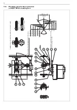
Page 23: ...N 9 10 11 8 2 5 4 3 1 7 6 12 13 14 LEVERARM SPRING POSITION TO BE AGAINST ACTUATOR PIN MAKE SURE THIS MARK ON THE LEVER ARM IS IN THE SAME QUADRANT AS THE MARK ON THE FLAT OF THE SHAFT C L ACTUATOR MID STROKE 3 4 1 1 1 8 1 1 2 2 1 4 3 1 2 3 4 1 1 1 8 1 1 2 2 1 4 3 1 2 4 4 5 5 IN INCHES STROKE 90 4 4 1 1 8 1 1 8 3 4 1 3 4 1 1 1 2 2 1 4 3 1 2 1 1 2 2 1 4 3 1 2 5 5 IN INCHES STROKE Item Qty Descripti...

Page 24: ...20 mm 21 4 30 mm 28 6 40 mm 35 7 50 mm 42 8 60 mm 50 70 mm 57 1 80 mm 64 3 90 mm 71 4 100 mm Stroke 20 100 mm Scale Distance from shaft center to carrier bolt according to stroke Feedback lever in horizontal position at mid travel of stroke The mark on the shaft should stay in this sector Stroke 20 60 mm Stroke 60 100 mm 24 ...

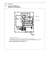
Page 25: ... K06B VALVE CONTROLLER ND800 A Open LS2 K Closed LS1 K06B with limit switch Connection diagram shows limit switch when actuator is in intermediate position Switch A upper is activated at the open limit of the travel and switch K lower at the cloised limit Micro switches OMRON D2VW 01 gold plated contacts Ambient temperature 40 85 C 40 185 F 25 ...

Page 26: ...e gland receptacles 1 Voltage brown 3 Voltage blue 4 Shield black 1 Voltage brown 3 Voltage blue 4 Shield grey ND84 P1 male eurofast type WEIDMÜLLER 945565 PG13 5 M12 ND84 P2 male minifast type TURCK RSFV48 13 5 26 ...

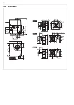
Page 27: ... 2 I M20x1 5 L 1 2NPT 137 137 39 5 26 47 5 5 39 1 02 1 87 0 98 0 23 1 02 1 18 5 39 1 55 1 22 1 10 0 59 C1 S C2 PG13 5 M6 10 1 4NPT ND800 S1 M6x12 33 33 23 23 4 3 23 5 21 25 117 35 4 35 4 F05 50 VDI VDE3845 1 39 0 98 4 60 1 30 1 30 0 90 0 12 0 90 0 93 1 39 0 16 0 83 27 ...

Page 28: ...L I NJ ND800 S1 ND800 S2 21 13 9 25 1 4 NPT 35 4 M6 10 26 30 5 6 UNC 13 5 29 4 M5 18 ND800A ø6 ø6 ø15 31 15 28 33 33 23 35 4 F05 50 ø VDI VDE 3845 26 8 C2 S C1 C2 S C1 C2 S C1 137 126 39 5 R1 2 M20x1 5 1 2 NPT 70 46 23 5 38 172 PG13 5 55 28 ...

Page 29: ... 20 60 mm or 60 100 mm 6 sign OPTIONS Standard IP 65 enclosure NEMA 4 and 4X Built in display and local keypad PG 13 5 conduit entry Without sign Temperature range 20 85 C 4 185 F Load voltage max 13 5 VDC at 20 mA corresponding 675 max voltage drop Supply voltage 30 VDC C Low temperature 40 C 40 F S1 Valve controller attachment face acc to standard VDI VDE 3845 equipped with an H clip When valve ...

Page 30: ......

Page 31: ......

Page 32: ... Fax int 1 832 590 5060 North America 3100 Medlock Bridge Road Suite 250 Norcross GA 30071 USA Tel int 1 770 446 7818 Fax int 1 770 242 8386 Latin America Av Central 181 Chácaras Reunidas 12238 430 São Jose do Campos Tel int 55 12 335 3500 Fax int 55 12 335 3535 Asia Pacific 501 Orchard Road 05 09 Wheelock Place 238880 Singapore Tel int 65 735 5200 Fax int 65 735 4566 www metsoautomation com ...

Reviews: