2.4
Mounting on linear actuators withMetso
Automation or IEC 60534 mounting face
See Sections 10.5, 10.6.
Connect an airset directly to the actuator and position the
actuator at its mid-stroke position (see serial plate for
actuator stroke length).
Attach the feedback arm on to the controller input shaft.
Make sure the lettering on the feedback arm faces up,
toward the controller.
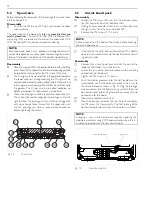
Attach the controller mounting bracket loosely on to the
slotted leg of the actuator. Make sure the marks on the
shaft and feedback arm operate in the quadrant shown.
Measure the distance from the centre of the feedback
lever shaft to the slot on the feedback lever and mark this
distance with a pencil or other marking instrument. Use
the dimensions given in Sections 10.5 and 10.6.
Mount the controller loosely onto the controller mounting
bracket.
Adjust the controller mounting bracket and the controller
so that the controller is at 90° to the centre line of the
actuator and the controller feedback lever is horizontal
and at 90° to the centre line of the actuator.
Tighten the controller mounting bracket screws.
Adjust the controller on the controller mounting bracket so
that the measured distance is maintained between the centre
of the feedback lever shaft and the actuator pin (pre-meas-
ured mark on the feedback lever). Note the controller must
still conform to the specifications in previous steps.
Tighten all the mounting bolts and then re-check that the
controller complies with previous steps. Check that the
actuator pin does not touch the controller case through-
out the entire stroke of the actuator. If the actuator pin is
too long it may be trimmed to length. (The pin must be
trimmed on stroke of 1.125" or less.)
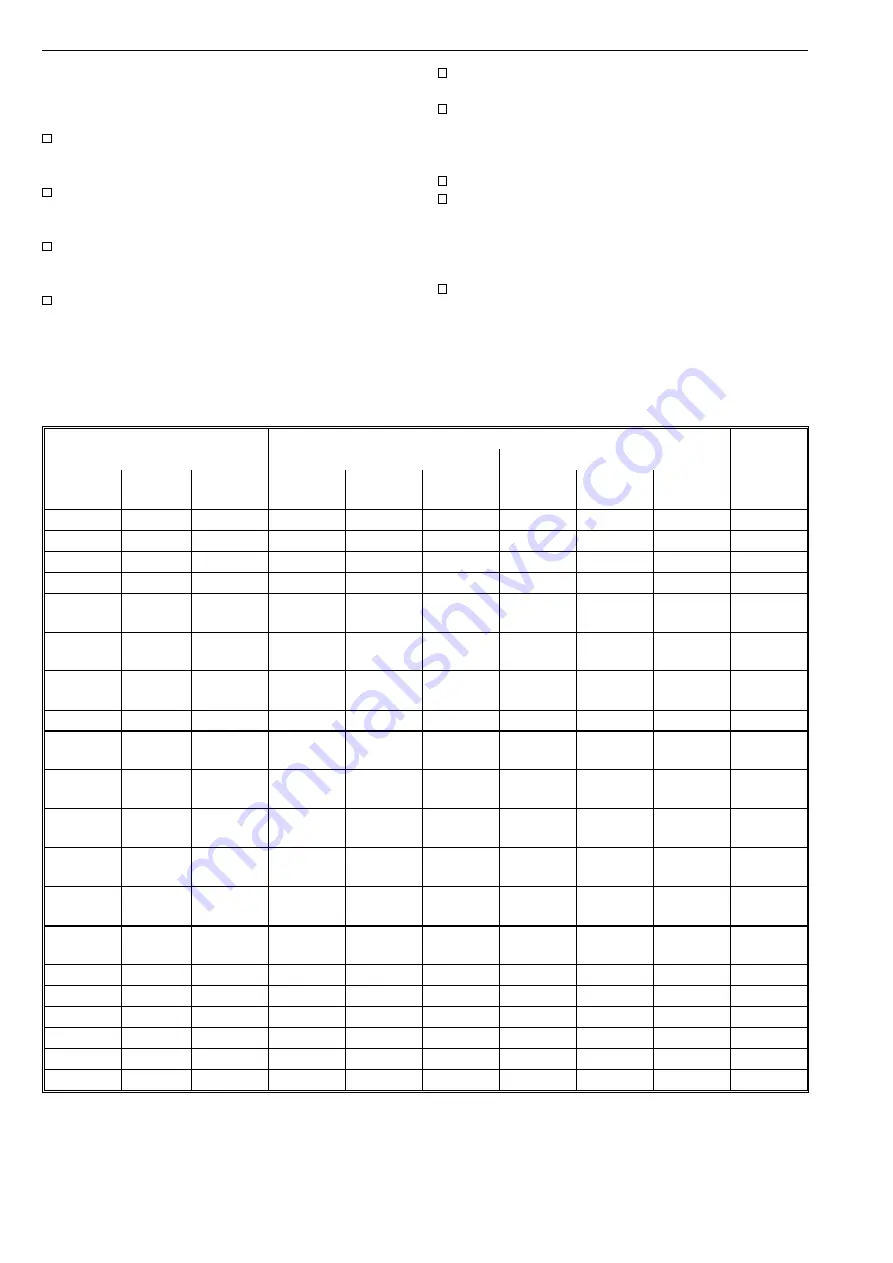
Actuator
Piping
Spool
valve
Plastic/Cu/SS (")
Plastic/Cu/SS (mm)
B1C
Stroke vol.
dm
3
/in
3
NPT
1/4
3/8
1/2
6/4
10/8
12/10
6
0.3/18
1/4
x
x
2
9
0.6/37
1/4
x
x
2
11
1.1/67
3/8
x
x
2
13
2.3/140
3/8
x
x
6
17
20
4.3/262
5.4/330
1/2
x
x
x
x
6
6
25
32
10.5/610
21/1282
1/2
3/4
x
x
(x)
(x)
x
x
(x)
(x)
6
6
40
50
43/2624
84/5126
3/4
1
(x)
(x)
x
x
x
x
6
6
502
195/11900
1
x
x
6
B1J
B1JA
Stroke vol.
dm
3
/in
3
NPT
1/4
3/8
1/2
6/4
10/8
12/10
Spool
valve
8
10
0.9/55
1.8/110
3/8
x
x
x
x
21
61
12
16
3.6/220
6.7/409
1/2
x
x
x
x
61
61
20
25
13/793
27/1648
3/4
x
x
(x)
(x)
x
x
(x)
(x)
61
61
32
322
53/3234
106/6468
1
(x)
x
x
x
x
61
61
QP
Stroke vol.
dm
3
/in
3
NPT
1/4
3/8
1/2
6/4
10/8
12/10
Spool
valve
1
0.62/37
3/8
x
x
21
2
1.08/66
3/8
x
x
21
3
2.18/133
3/8
x
x
61
4
4.34/265
3/8
x
x
61
5
8.7/531
3/8
x
x
61
6
17.5/1068
3/4
x
x
61
Table 1.
Piping
6


