background image

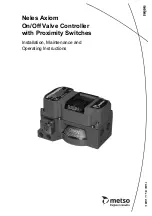
Neles Axiom
On/Off Valve Controller
with Proximity Switches

Installation, Maintenance and
Operating Instructions

7

 AMI 70 e

n

 • 2/20

10

Summary of Contents for Neles Axiom

Page 1: ...Neles Axiom On Off Valve Controller with Proximity Switches Installation Maintenance and Operating Instructions 7 AMI 70 en 2 2010 ...

Page 2: ...ng and disposal 5 1 6 Safety precautions 5 2 ASSEMBLY AND MOUNTING 5 3 SENSING AND COMMUNICATIONS MODULE SENSOR SETTING 6 3 1 Bench testing 6 3 2 Fault alerts for AMI96_D 7 3 3 Additional features for AMI96_D 8 4 EXPLODED VIEW 9 5 DIMENSIONS 10 6 WIRING DIAGRAMS 11 6 1 Type AMI33 11 6 2 Type AMI44 11 6 3 Type AMI96 12 6 4 Type AMI96_D 12 6 5 Type AMI97 12 6 6 Type AMI93 13 6 7 Type AMI94 13 6 8 In...

Page 3: ...guration 2 Discrete inputs Open and Closed 2 Auxiliary discrete inputs 1 Discrete output Drive solenoid 4 AS I version 2 1 Input voltage 26 5 to 31 V DC Devices per network 62 FOUNDATION fieldbus VCT bus powered 93 Configuration 2 Discrete inputs Open and Closed 2 Discrete outputs Drive Piezo 3 Current input 16 mA quiescent Voltage range 9 to 32 V DC Other features Stores number of actuations Stor...

Page 4: ...ype code General specifications and ratings Materials of construction Housing and mounting manifold Epoxy coated anodized aluminum Cover and visual indicator Lexan polycarbonate Fasteners and mounting adaptors Stainless steel Pneumatic valve See Pneumatic valve specifications below Temperature ratings pneumatic valve dependent Piezo pilots A 10 to 60 C Solenoid pilots D E H 18 to 50 C Special sole...

Page 5: ...ock Next place the Visual Indicator Drum Item 7 onto the Visual Indicator Drum Coupler Align the holes in all three items with the the threaded hole in the actuator shaft and fasten down with the Visual Indicator Drum Retaining Screw Item 9 Leave screw loose in order to facilitate indexing of the vis ual indicator 7 With the actuator in the closed position center the Visual Indicator Drum until th...

Page 6: ...ase button Set points are retained even after power is removed To test solenoid apply power to the Sol Pwr IN termi nals only See warning below NOTE If using only one of the sensors for valve posi tion feedback the open sensor green must be used Type AMI44 Power must be applied to both sensors to ensure proper circuit operation Use a 24 V DC power supply A series load resistor is not required when...

Page 7: ...oes not move by a minimum of 10 of stroke provided there is not a STUCK SPOOL PILOT or LOW AIR SUPPLY PRESSURE fault already indi cated Input Bit 2 DI 1 will be set to 1 A STUCK PROCESS VALVE ACTUATOR fault will also be indi cated if the valve actuator doe not reach the com manded position within 20 seconds Valve open position when solenoid coil is energized or valve closed position when solenoid ...

Page 8: ...it is ready to resume normal operation Remote Sensor Setting Feature The Axiom with Diagnostics provides the capability of setting the Closed and Open sensors remotely from the Control System or from the AS Interface Gateway Mas ter 1 AS Interface communications are required in order to remotely set the sensors The unit must be addressed and correctly configured to be recog nized by the Control Sy...

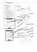
Page 9: ...ION QTY 1 Axiom Cover Screws 4 2 Axiom Cover 1 3 Axiom Body Screws 4 4 Axiom Body 1 5 DA SR Plug 1 6 Visual Indicator Cover 1 7 Visual Indicator Drum 1 8 Visual Indicator Drum Coupler 1 Item 9 thru 14 are provided with the mounting kit Mounting kits are sold separately 9 Visual Indicator Drum Retaining Screw 1 10 Visual Indicator Drive Block 1 11 Air Manifold Plate Mounting Screws 4 12 Air Manifol...

Page 10: ...10 7 AMI 70 en 5 DIMENSIONS E3 S1 E2 ...

Page 11: ...6 1 5 6 PIN MICRO CONNECTOR MALE PINS 4 3 2 6 1 5 PIN SIGNAL 1 OPEN CLOSED C 2 CLOSED NO 3 OPEN NO 4 SOL1 SOL2 PWR IN 5 SOL1 PWR IN 6 SOL2 PWR IN Closed 7 Closed 8 Open 6 Open 5 Sol Pwr 4 Sol Pwr 3 Sol 2 Sol 1 NAMUR SET OPEN SET CLOSED OPEN CLOSED SOLENOID POWER Setup Instructions Operate Actuator to Closed Position and Push SET CLOSED for 2 seconds Operate Actuator to Open Position and Push SET O...

Page 12: ...TUCK PROCESS VALVE ACTUATOR LOW AIR SUPPLY PRESSURE Diagnostics Blinking LED indicates problem Setup Instructions Operate Actuator to Closed Position and Push SET CLOSED for 2 seconds Operate Actuator to Open Position and Push SET OPEN for 2 seconds PIN SIGNAL 1 ASI 2 Not Used 3 ASI 4 Not Used 4 PIN MICRO CONNECTOR MALE PINS 4 3 2 1 4 PIN MINI CONNECTOR MALE PINS 1 3 4 2 Aux IN 1 7 Aux IN 8 Aux IN...

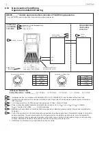
Page 13: ...IGNAL 1 FB 2 FB 3 Not Used 4 Not Used 4 PIN MICRO CONNECTOR MALE PINS 4 3 2 1 4 PIN MINI CONNECTOR MALE PINS 1 3 4 2 24 VDC 8 FB 9 24 VDC 7 OUT 1 6 OUT 1 5 OUT 2 4 OUT 2 3 SIM JMPR 1 SET OPEN SET CLOSED OPEN CLOSED SOLENOID POWER Setup Instructions Operate Actuator to Closed Position and Push SET CLOSED for 2 seconds Operate Actuator to Open Position and Push SET OPEN for 2 seconds SIM JMPR 2 FB 1...

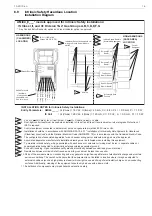
Page 14: ...onducting and may generate an ignition capable level of electrostatic charge under certain extreme conditions The user should ensure that the equipment is not installed in location where it may be subjected to external conditions such as high pressure steam which might cause a build up of electrostatic charge on non conducting surfaces Additionally cleaning of the equipment should only be done wit...

Page 15: ...installation verify electrical continuity between conduit and ground terminal 9 Resistance between Intrinsic Safe Ground and earth ground must be less than one ohm 10 Parts of the enclosure are non conducting and may generate an ignition capable level of electrostatic charge under certain extreme conditions The user should ensure that the equipment is not installed in location where it may be subj...

Page 16: ...nder certain extreme conditions The user should ensure that the equipment is not installed in location where it may be subjected to external conditions such as high pressure steam which might cause a build up of electrostatic charge on non conducting surfaces Additionally cleaning of the equipment should only be done with a damp cloth 7 Substitution of components may impair hazardous location safe...

Page 17: ...der certain extreme conditions The user should ensure that the equipment is not installed in location where it may be subjected to external conditions such as high pressure steam which might cause a build up of electrostatic charge on non conducting surfaces Additionally cleaning of the equipment should only be done with a damp cloth 7 Substitution of components may impair hazardous location safet...

Page 18: ...jected to external conditions such as high pressure steam which might cause a build up of electrostatic charge on non conducting surfaces Additionally cleaning of the equipment should only be done with a damp cloth 7 Substitution of components may impair hazardous location safety 8 Approval Agency controlled Installation Diagram No revision to diagram allowed without prior Factory Mutual or Approv...

Page 19: ... sign D 4 Manual override Not applicable to 7 sign D 4 PNEUMATIC VALVE Solenoid Temperature range 18 to 50 C H 24 V DC 120 V AC 0 6 W Applicable to 2 sign 33 E 12 V DC 0 5 W intrinsically safe Applicable to 2 sign 44 D 24 V DC 0 5 W Applicable to 2 sign 94 96 or 97 Piezo Temperature range 10 to 60 C A 6 5 V DC 2 mA intrinsically safe Applicable to 2 sign 93 5 ENCLOSURE Standard IP67 enclosure V AT...

Page 20: ...ocaba São Paulo Brazil Tel 55 15 3235 9700 Fax 55 15 3235 9748 49 Asia Pacific 238A Thomson Road 25 09 Novena Square Tower A 307684 Singapore Tel 65 6511 1011 Fax 65 6250 0830 China 19 F the Exchange Beijing No 118 Jianguo Lu Yi Chaoyang Dist 100022 Beijing China Tel 86 10 6566 6600 Fax 86 10 6566 2575 Middle East Roundabout 8 Unit AB 07 P O Box 17175 Jebel Ali Freezone Dubai United Arab Emirates ...

Reviews: