IMO 3/20
4
IMO-502 EN
4.
INSTALLATION PROCEDURE
The equipment must be installed in the accordance with the
laws, guide lines and rules applicable within the country.
As per ISO 8573 we required air quality as below.
1. Particle size < 5 μ (class 5)
2. Pressure dew point < -20°C (class 3) for actuator
3. Pressure dew point < -40°C (Class 4) for positioner
4. Concentration of total oil < 5 mg/m
3
WARNING:
OPERATING CYLINDERS OVER TEMPERATURE OR PRESSURE LIMITS
WILL RESULT IN DAMAGE TO CYLINDERS.
CAUTION: DO NOT DISMANTLE THE CYLINDER WHILE
OPERATION IS IN LINE. DO NOT ALLOW DIRTY AIR OR FLUIDS
TO GET INTO THE CYLINDER. USE FILTER UNIT (FILTER SIZE
40ΜM, 3°C) FOR DUST AND MOISTURE REMOVAL.
NOTE: Ensure the installation meets the legal and regulatory
requirements of the country and state of use.The cylinder
assembly should be left in the original packing until it is
required for the use. The metallic pipe connections should
be rinsed with degreasing or by grease dissolving liquids
or agents, before being connected to our cylinder. Flush all
pipes with 4 kgf/cm
2
air for at least 1/2 hour. Lubrication is
not necessary. (Maintain once started oil mist lubrication. As
per ISO 3448 recommended oils are NUTO H 32, VG 32. Oil
viscosity 32 cSt at 40°C). Operating pressure range 1-10 bar.
Operating temperature range -20°C to +70°C
1. Pneumatic system is suitable for operation with
compressed air between 1-10 bar. Usually the sizing is
done at the air pressure availability confirmed by the
client. (Hydraulic pressure maximum of 10 bar on request)
2. Hemp filaments, jute or even teflon ribbons are
normally not required, As the part connections are
accurately threaded. By chance, if any of these or any
other tightening medium get into the operational area
inside the cylinder, possible damage of the cylinder
could not be ruled out.
3. The mounting holes size and bolt size circle are
confirming to ISO 6431 / ISO 15552 norms. The threaded
holes are ISO metric coarse and as ISO 6431 / ISO 15552.
(Refer catalogue)
4. Clean all pipes and tube fittings thoroughly with suitable
means. As even when brand new pipes are fitted, unclean
interior are quite covered with dirt and dust.
5. Avoid impact on the cylinder. These may happen during
transportation/ erection/ mishandling.
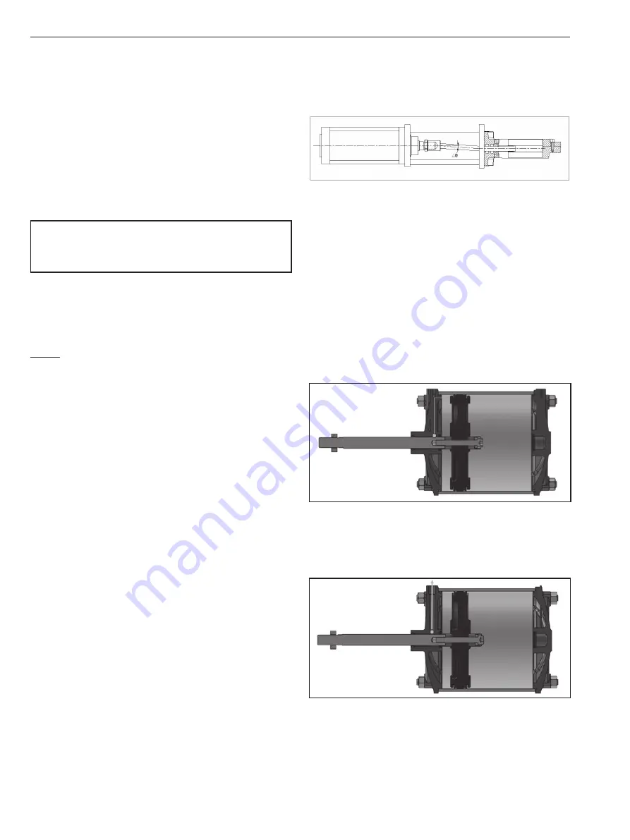
6. Align properly the rod axis with the load and direction
of movement when connecting. If not properly aligned,
the rod and tube may be twisted and damage may be
caused due to wear on areas such as inner tube surface,
bushing, rod surface and seals.
7. All accessories mountings of cylinders are well
lubricated before dispatch. After removing pin and
circlip store them in clean box. Install pin and circlips
without damaging bore.
8. When an external guide is used, connect the rod end
and the load in such a way that there is no interference
at any point within the stroke.
9. Cushioning –
When stroke comes to an end, cushioning allows air to pass
through cushioning port and thus decelerate the piston
before it strikes the end cap which lowers the stresses on
cylinder components and reduces vibration transmitted to
the machine structure.
If cushioning is not provided then air passes through
exhaust port only. When stroke comes to an end, piston
strikes the end cover with some acceleration, giving rise
to knocking noise, stresses on cylinder components and
vibration transmitted to the machine structure.
Perfect pneumatic cushioning produces minimal noise from
end cover contact, and minimum piston deceleration time.
To achieve perfect cushioning, ensure cushioning screw is
full open at the time of installation. Operate cylinder in full
forward to full back. Now keep on tightening cushioning
screw till cylinder stops knocking. This will give maximum
life to your equipment and to pneumatic cylinder.
Cylinder
Gate valve
Misalignment by angle θ
Summary of Contents for JAMESBURY CC Series
Page 11: ...IMO 3 20 IMO 502 EN 11 ...


