background image


  IMO 3/20


IMO-502 EN 

3

1. 

INTRODUCTION

Thank you for choosing METSO product. Each product 

is fully inspected after the production to offer you the 

highest quality. In order to fully utilize the product, we 

strongly recommend users to read this manual carefully and 

understood.

This manual provides information on installation, operation 

and maintenance procedures and related instructions for 

the RMEBS make pneumatic cylinder (CC series). 

The aim of this literature is to support the use of products in 

correct manner, and all the technical information provided 

in the catalogue.

The manual should be given to the end user.

The manual can be changed or revised without any prior 

notice. Any changes in product’s specification, structure, 

and/or any components may not result immediate revised 

version of the manual.

The manual should not be duplicated or reproduced for any 

purpose without any consent of RMEBS Manufacturers & 

Engineers Private Limited, INDIA.

Manufacturer Warranty

For the safety, it is vital to follow instructions in the manual. 

It is not RMEBS’s liability for any damages which caused by 

users’ negligence.

It is not RMEBS’s liability for any damages or accidents which 

resulted by any alteration or modification of the product 

and parts. If alteration or modification is necessary, please 

contact the RMEBS directly.

RMEBS warrants the product from the date of original 

retail purchase of the product for one (1) year, except as 

otherwise stated.

RMEBS warranty will not cover the products that the 

product have been subjected to abuse, accident, alteration, 

modification, tampering, negligence, misuse, faulty 

installation, lack of reasonable care, repair or service in any 

way that is not contemplated in the documentation for the 

product, or if the model or serial number has been altered, 

tampered with, defaced or removed; damages that occurs 

in shipment, failure due to power surge, and cosmetic 

damage. Improper or incorrectly performed maintenance 

or report voids this Limited Warranty.

For detailed warranty information, please contact : 

RMEBS MANUFACTERURS & ENGINEERS PRIVATE LIMITED, 

Manapada road, Dombivli (e), Maharashtra, India, Pin - 421204

1.1 

Definitions

WARNING:

IF NOT OBSERVED, USER INCURS A HIGH RISK OF SEVERE DAMAGE 

TO PRODUCT AND/OR FATAL INJURY TO PERSONNEL. 

CAUTION: IF NOT OBSERVED, USER MAY INCUR DAMAGE 

TO PRODUCT AND/OR INJURY TO PERSONNEL. 

NOTE: Advisory and information comments provided to assist 

maintenance personnel to carry out maintenance procedures.

2. 

OPERATION PRINCIPAL

Pneumatic cylinder is a mechanical device which uses power 

of compressed air/gas to produce a force in a reciprocating 

linear motion.

The basic pneumatic cylinder consists of a cylindrical chamber 

with a movable piston and intake and exhaust channels. 

Compressed air or other gas is supplied into the cylindrical 

chamber. This pressurized air/gas exerts force against the 

base of the piston, which causes piston to move, providing 

a way to move other mechanical elements. 
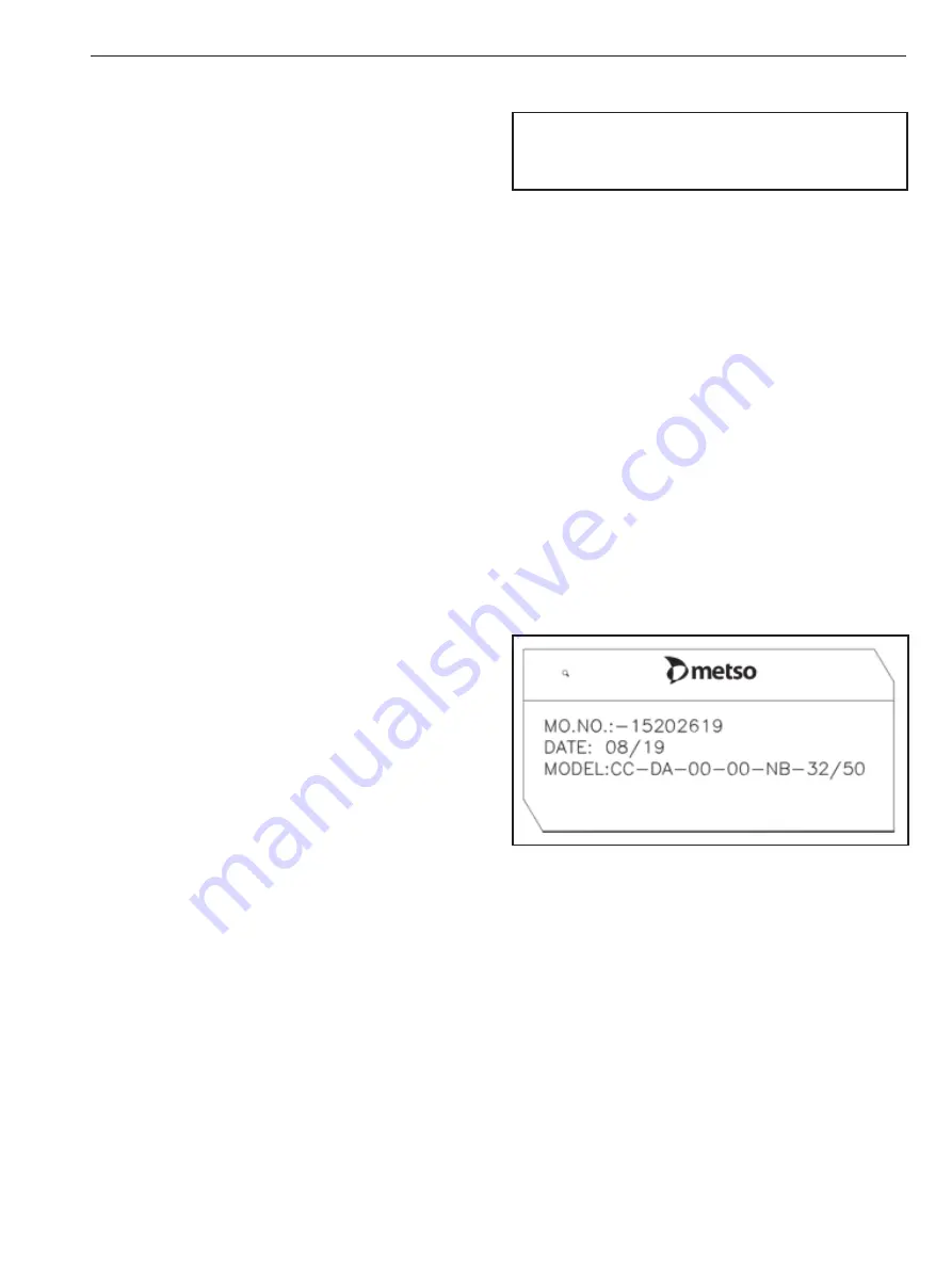
3. 

LABEL DESCRIPTION

Label of the cylinder defines the precise feature of that 

particular cylinder. This description is written below the 

METSO logo and is as follow.

M.O. NO.: 

Manufacturing order number

DATE:  

Date of manufacturing

Model no.:   CC – Type
 

DA   – Double acting cylinder


00 – standard MOC of piston rod


00 – Standard model


NB – Piston diameter 350 mm


32 – Stroke length 250 mm


50 – Stroke length 250 mm

Summary of Contents for JAMESBURY CC Series

Page 1: ...IMO 502 EN 3 2020 JAMESBURY EASYFLOW PNEUMATIC CYLINDER CC SERIES Ø200 Ø350 Installation Maintenance and Operating Instructions ...

Page 2: ...ck cover See also www metso com valves for the latest documentation SAVE THESE INSTRUCTIONS TABLE OF CONTENTS 1 INTRODUCTION 3 1 1 Definitions 3 2 OPERATION PRINCIPAL 3 3 LABEL DESCRIPTION 3 4 INSTALLATION PROCEDURE 4 5 MAINTENANCE 5 6 TOOL KIT 5 7 DISASSEMBLY 5 7 1 Front cover disassembly 6 7 2 Piston disassembly 6 7 3 Rear cover disassembly 7 8 ASSEMBLY 7 8 1 Rear cover assembly 7 8 2 Piston ass...

Page 3: ...tion tampering negligence misuse faulty installation lack of reasonable care repair or service in any way that is not contemplated in the documentation for the product or if the model or serial number has been altered tampered with defaced or removed damages that occurs in shipment failure due to power surge and cosmetic damage Improper or incorrectly performed maintenance or report voids this Lim...

Page 4: ... ruled out 3 The mounting holes size and bolt size circle are confirming to ISO 6431 ISO 15552 norms The threaded holes are ISO metric coarse and as ISO 6431 ISO 15552 Refer catalogue 4 Clean all pipes and tube fittings thoroughly with suitable means Asevenwhenbrandnewpipesarefitted unclean interior are quite covered with dirt and dust 5 Avoid impact on the cylinder These may happen during transpo...

Page 5: ...t operating 1 Compressed air is not available Make it available 2 Side thrust is too high Align the component properly 3 Operating below the lower speed limit Eliminate cause of lower load fluctuation 4 Direction control valve is not operating Makesurethatthepressure and supplied voltage for direction control valve are as per rating 5 Connected device Gate valve globe valve damper etc get stucked ...

Page 6: ...bly 1 Remove lock nut 7 Loosen the cylinder cover bolt 9 of front cover and remove it 2 Remove rod seal 14 using screw driver 3 Remove o ring 17 and cushion seal 15 take out cushioningscrew 12 wiitho ring 19 fromfrontcover 1 4 Clean it with liquid soap solution After drying apply grease on rubber parts Replace these rubber parts 5 Pull the piston rod 5 with piston subassembly outside the tube 3 6 ...

Page 7: ...he vertical position This is required to ensure that springs remain properly aligned and centred during assembly For single acting cylinder follow the sequences as given below to ensure proper assembly For double acting cylinder just ignore the 5th step in heading 8 2 Piston assembly follow the sequence to ensure proper assembly 8 1 Rear cover assembly 1 Clean it with liquid soap solution After dr...

Page 8: ... tube 3 8 3 Front cover assembly 1 Clean it with liquid soap solution After drying apply RMEBS grease rubber parts 2 Place rod seal 14 on its groove 3 Place Cushioning seal 15 and o ring 17 on its groove Place o ring 19 on cushioning screw 12 assemble the cushioning screw on rear cover 2 4 Assembled the front cover 1 on the tube 3 fasten the cylinder cover nut 9 and engage the lock nut 7 NOTE Oper...

Page 9: ...ity 1 FRONT COVER 1 2 REAR COVER 1 3 CYLIDER TUBE 1 4 PISTON 1 5 PISTON ROD 1 6 TIE ROD 4 7 NUT 1 8 SHC SCREW 1 9 NUT 8 10 BUFFER CAP 2 11 PISTON STRIP 1 12 CUSHIONING PLUG 2 13 WASHER 1 14 ROD SEAL 1 15 CUSHIONING SEAL 2 16 SEALS 2 17 SEALS 2 18 BUSH 1 19 O RING 2 ...

Page 10: ... prevent moisture or dust from contacting product 2 CYLINDER ASSEMBLY should be stored in a dry place free from water and dust 3 Store at temperature between 40 F and 120 F 4 C and 49 C 4 Locate in an area to avoid damage by impact 11 ASSISTANCE Fortechnicalquestionsorassistance contactanyauthorized distributor of RMEBS Private limited or ...

Page 11: ...IMO 3 20 IMO 502 EN 11 ...

Page 12: ...oration Töölönlahdenkatu 2 PO Box 1220 00100 Helsinki Finland Tel 358 20 484 100 http contact metso com Neles Finland Inc Vanha Porvoontie 229 P O Box 304 FI 01301 Vantaa Finland Tel 358 20 483 150 Fax 358 20 483 151 www metso com valves 12 IMO 503 EN ...

Reviews: