background image


IMO 3/20

IMO-502 EN

4. 

INSTALLATION PROCEDURE

The equipment must be installed in the accordance with the 

laws, guide lines and rules applicable within the country.

As per ISO 8573 we required air quality as below.

1.  Particle size < 5 μ (class 5)

2.  Pressure dew point < -20°C (class 3) for actuator 

3.  Pressure dew point < -40°C (Class 4) for positioner

4.  Concentration of total oil < 5 mg/m

3

WARNING:

OPERATING CYLINDERS OVER TEMPERATURE OR PRESSURE LIMITS 

WILL RESULT IN DAMAGE TO CYLINDERS.

CAUTION: DO NOT DISMANTLE THE CYLINDER WHILE 

OPERATION IS IN LINE. DO NOT ALLOW DIRTY AIR OR FLUIDS 

TO GET INTO THE CYLINDER. USE FILTER UNIT (FILTER SIZE 

40ΜM, 3°C) FOR DUST AND MOISTURE REMOVAL. 

NOTE: Ensure the installation meets the legal and regulatory 

requirements of the country and state of use.The cylinder 

assembly should be left in the original packing until it is 

required for the use. The metallic pipe connections should 

be rinsed with degreasing or by grease dissolving liquids 

or agents, before being connected to our cylinder. Flush all 

pipes with 4 kgf/cm

2

 air for at least 1/2 hour. Lubrication is 

not necessary. (Maintain once started oil mist lubrication. As 

per ISO 3448 recommended oils are NUTO H 32, VG 32. Oil 

viscosity 32 cSt at 40°C). Operating pressure range 1-10 bar. 

Operating temperature range -20°C to +70°C

1.  Pneumatic system is suitable for operation with 

compressed air between 1-10 bar. Usually the sizing is 

done at the air pressure availability confirmed by the 

client. (Hydraulic pressure maximum of 10 bar on request)

2.  Hemp filaments, jute or even teflon ribbons are 

normally not required, As the part connections are 

accurately threaded. By chance, if any of these or any 

other tightening medium get into the operational area 

inside the cylinder, possible damage of the cylinder 

could not be ruled out.

3.  The mounting holes size and bolt size circle are 

confirming to ISO 6431 / ISO 15552 norms. The threaded 

holes are ISO metric coarse and as ISO 6431 / ISO 15552. 

(Refer catalogue)

4.  Clean all pipes and tube fittings thoroughly with suitable 

means. As even when brand new pipes are fitted, unclean 

interior are quite covered with dirt and dust.

5.  Avoid impact on the cylinder. These may happen during 

transportation/ erection/ mishandling.

6.  Align properly the rod axis with the load and direction 

of movement when connecting. If not properly aligned, 

the rod and tube may be twisted and damage may be 

caused due to wear on areas such as inner tube surface, 

bushing, rod surface and seals.

7.  All accessories mountings of cylinders are well 

lubricated before dispatch. After removing pin and 

circlip store them in clean box. Install pin and circlips 

without damaging bore.

8.  When an external guide is used, connect the rod end 

and the load in such a way that there is no interference 

at any point within the stroke.

9.  Cushioning – 

When stroke comes to an end, cushioning allows air to pass 

through cushioning port and thus decelerate the piston 

before it strikes the end cap which lowers the stresses on 

cylinder components and reduces vibration transmitted to 

the machine structure.

If cushioning is not provided then air passes through 

exhaust port only. When stroke comes to an end, piston 

strikes the end cover with some acceleration, giving rise 

to knocking noise, stresses on cylinder components and 

vibration transmitted to the machine structure.

Perfect pneumatic cushioning produces minimal noise from 

end cover contact, and minimum piston deceleration time.  

To achieve perfect cushioning, ensure cushioning screw is 

full open at the time of installation. Operate cylinder in full 

forward to full back. Now keep on tightening cushioning 

screw till cylinder stops knocking. This will give maximum 

life to your equipment and to pneumatic cylinder.
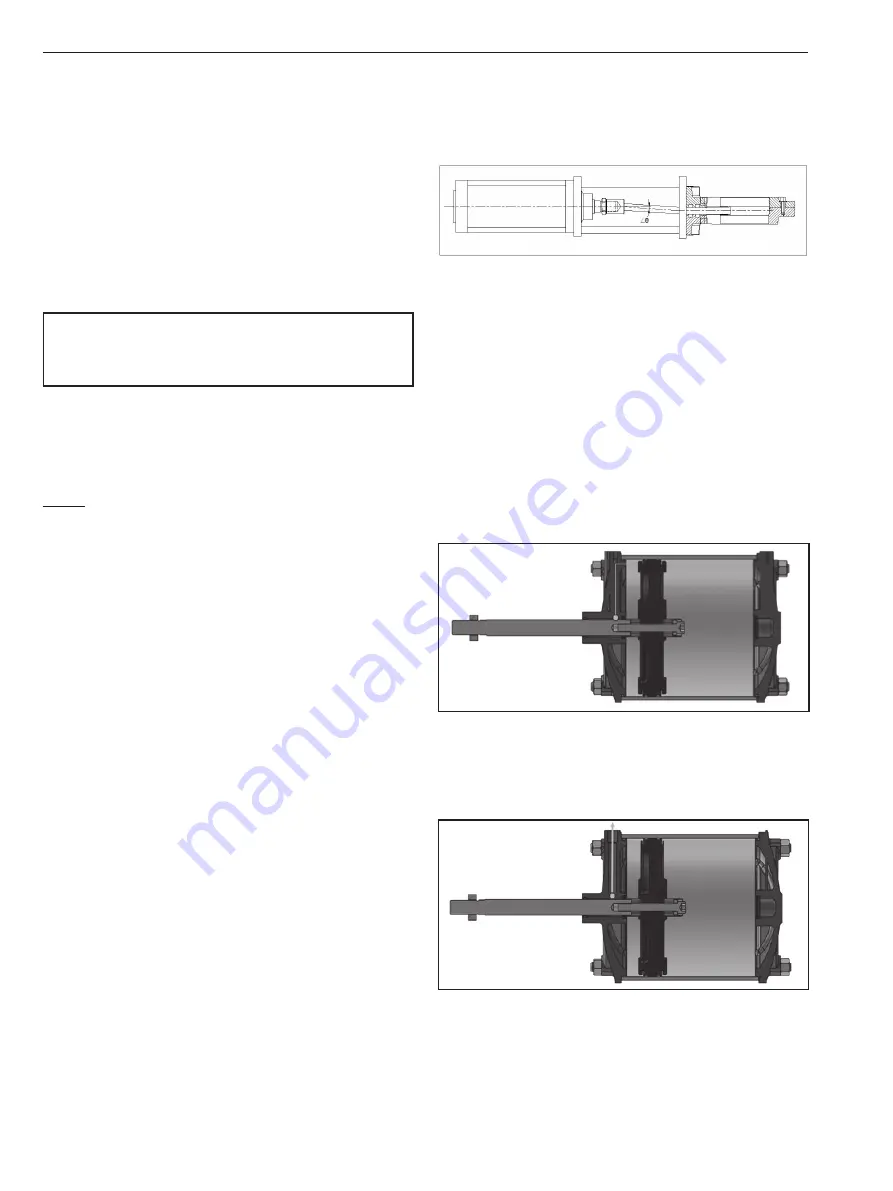
Cylinder

Gate valve

Misalignment by angle θ

Summary of Contents for JAMESBURY CC Series

Page 1: ...IMO 502 EN 3 2020 JAMESBURY EASYFLOW PNEUMATIC CYLINDER CC SERIES Ø200 Ø350 Installation Maintenance and Operating Instructions ...

Page 2: ...ck cover See also www metso com valves for the latest documentation SAVE THESE INSTRUCTIONS TABLE OF CONTENTS 1 INTRODUCTION 3 1 1 Definitions 3 2 OPERATION PRINCIPAL 3 3 LABEL DESCRIPTION 3 4 INSTALLATION PROCEDURE 4 5 MAINTENANCE 5 6 TOOL KIT 5 7 DISASSEMBLY 5 7 1 Front cover disassembly 6 7 2 Piston disassembly 6 7 3 Rear cover disassembly 7 8 ASSEMBLY 7 8 1 Rear cover assembly 7 8 2 Piston ass...

Page 3: ...tion tampering negligence misuse faulty installation lack of reasonable care repair or service in any way that is not contemplated in the documentation for the product or if the model or serial number has been altered tampered with defaced or removed damages that occurs in shipment failure due to power surge and cosmetic damage Improper or incorrectly performed maintenance or report voids this Lim...

Page 4: ... ruled out 3 The mounting holes size and bolt size circle are confirming to ISO 6431 ISO 15552 norms The threaded holes are ISO metric coarse and as ISO 6431 ISO 15552 Refer catalogue 4 Clean all pipes and tube fittings thoroughly with suitable means Asevenwhenbrandnewpipesarefitted unclean interior are quite covered with dirt and dust 5 Avoid impact on the cylinder These may happen during transpo...

Page 5: ...t operating 1 Compressed air is not available Make it available 2 Side thrust is too high Align the component properly 3 Operating below the lower speed limit Eliminate cause of lower load fluctuation 4 Direction control valve is not operating Makesurethatthepressure and supplied voltage for direction control valve are as per rating 5 Connected device Gate valve globe valve damper etc get stucked ...

Page 6: ...bly 1 Remove lock nut 7 Loosen the cylinder cover bolt 9 of front cover and remove it 2 Remove rod seal 14 using screw driver 3 Remove o ring 17 and cushion seal 15 take out cushioningscrew 12 wiitho ring 19 fromfrontcover 1 4 Clean it with liquid soap solution After drying apply grease on rubber parts Replace these rubber parts 5 Pull the piston rod 5 with piston subassembly outside the tube 3 6 ...

Page 7: ...he vertical position This is required to ensure that springs remain properly aligned and centred during assembly For single acting cylinder follow the sequences as given below to ensure proper assembly For double acting cylinder just ignore the 5th step in heading 8 2 Piston assembly follow the sequence to ensure proper assembly 8 1 Rear cover assembly 1 Clean it with liquid soap solution After dr...

Page 8: ... tube 3 8 3 Front cover assembly 1 Clean it with liquid soap solution After drying apply RMEBS grease rubber parts 2 Place rod seal 14 on its groove 3 Place Cushioning seal 15 and o ring 17 on its groove Place o ring 19 on cushioning screw 12 assemble the cushioning screw on rear cover 2 4 Assembled the front cover 1 on the tube 3 fasten the cylinder cover nut 9 and engage the lock nut 7 NOTE Oper...

Page 9: ...ity 1 FRONT COVER 1 2 REAR COVER 1 3 CYLIDER TUBE 1 4 PISTON 1 5 PISTON ROD 1 6 TIE ROD 4 7 NUT 1 8 SHC SCREW 1 9 NUT 8 10 BUFFER CAP 2 11 PISTON STRIP 1 12 CUSHIONING PLUG 2 13 WASHER 1 14 ROD SEAL 1 15 CUSHIONING SEAL 2 16 SEALS 2 17 SEALS 2 18 BUSH 1 19 O RING 2 ...

Page 10: ... prevent moisture or dust from contacting product 2 CYLINDER ASSEMBLY should be stored in a dry place free from water and dust 3 Store at temperature between 40 F and 120 F 4 C and 49 C 4 Locate in an area to avoid damage by impact 11 ASSISTANCE Fortechnicalquestionsorassistance contactanyauthorized distributor of RMEBS Private limited or ...

Page 11: ...IMO 3 20 IMO 502 EN 11 ...

Page 12: ...oration Töölönlahdenkatu 2 PO Box 1220 00100 Helsinki Finland Tel 358 20 484 100 http contact metso com Neles Finland Inc Vanha Porvoontie 229 P O Box 304 FI 01301 Vantaa Finland Tel 358 20 483 150 Fax 358 20 483 151 www metso com valves 12 IMO 503 EN ...

Reviews: