SECTION 2 - GENERAL INSTALLATION INFORMATION
MP SERIES CONE CRUSHER TECHNICAL REFERENCE MANUAL
2-27
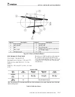
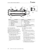
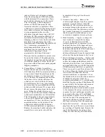
Figure 2-15 End Float - Direct Drive
Initial Alignment Of Flexible Coupling
For the initial installation or when reassembling the
flexible coupling on a direct arrangement, it is
always desirable to align the couplings as
accurately as possible for the longest coupling life
and minimum vibration. After the coupling halves
have been properly installed on the shafts, bring the
two halves together and proceed to align the
coupling as follows:
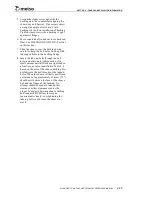
1. Check the gap and angular alignment by
measuring the distance between the coupling
halves, at four places, 90° apart, around the
circumference of the coupling as shown on
Figure 2-16. To measure the gap, use a
feeler gauge or inside calipers or a dial
indicator with a magnetic base. Coupling
halves must be aligned so that all four
measured dimensions DO NOT vary more
than 0.38 mm (0.015").
If any of the four measured dimensions
varies more than the 0.38 mm (0.015"), it
would indicate excessive angular
misalignment.
2. Check parallel alignment by laying a
straight edge across the outside diameter of
the coupling halves, at four places, 90°
apart, around the circumference of the
coupling. See Figure 2-16. Align so that the
straight edge rests squarely on both coupling
halves. Check with a feeler gauge or with a
dial indicator. Parallel misalignment should
NOT exceed 0.38 mm (0.015").
3. Gap, angular and parallel alignment are
important whenever using a flexible
coupling to drive a Crusher.
4. A safety set collar must be installed on the
crusher countershaft to provide the proper
countershaft end float or running clearance.
Refer to the instructions in
Section 4
for the
proper installation of set collar.
Callout
Description
Callout
Description
1
Pinion
5
Flexible Coupling
2
Inner Countershaft Bushing
6
Safety Set Collar
3
Outer Countershaft Bushing
7
Tight
4
Oil Flinger
Summary of Contents for MP1000
Page 1: ...Nordberg MP Series Cone Crusher ...
Page 2: ......
Page 4: ......
Page 6: ......
Page 8: ......
Page 64: ...SECTION 0 SAFETY 0 56 MP SERIES CONE CRUSHER TECHNICAL REFERENCE MANUAL ...
Page 66: ......
Page 74: ......
Page 154: ...Countershaft and Countershaft Box Callout Description 1 Countershaft 2 Countershaft box 1 2 ...


