SECTION 3 - M. FRAME, ADJ. RING, TRAMP REL. & CLRNG JACK ASSY
3-18
MP SERIES CONE CRUSHER TECHNICAL REFERENCE MANUAL
2. Lock out and tag all electrical power
supplied to the power unit and Crusher and
depressurize the clamping and tramp release
circuits by opening the clamping cylinder
and tramp release cylinder needle valves
located on the side of the hydraulic power
unit at the hose connection area. Verify that
the pressure gauges (PI-1 for the clamping
cylinder circuit and PI-2 for the tramp
release circuit) read zero pressure.
3. Disconnect the release circuit hoses on both
sides of the tramp release cylinder. If the
release cylinder to be removed has the hose
from the power unit connected to it, remove
the hose from the elbow on front of the
cylinder as well. Refer to Figure 3-15. Cap
or plug open ports and hose ends to prevent
loss of oil and entry of dirt.
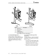
Figure 3-15 Tramp Release Cylinder and Accumulator
Callout
Description
Callout
Description
1
Rod nut
6
Tramp release cylinder
2
Bearing cone
7
Accumulator
3
Bearing cup
8
Rod seal
4
Hose connection
9
Bumper
5
Clamp segment
MP1000
MP800
1
2
3
8
3
2
4
6
5
7
9
4
5
Summary of Contents for MP1000
Page 1: ...Nordberg MP Series Cone Crusher ...
Page 2: ......
Page 4: ......
Page 6: ......
Page 8: ......
Page 64: ...SECTION 0 SAFETY 0 56 MP SERIES CONE CRUSHER TECHNICAL REFERENCE MANUAL ...
Page 66: ......
Page 74: ......
Page 154: ...Countershaft and Countershaft Box Callout Description 1 Countershaft 2 Countershaft box 1 2 ...

