SECTION 2 - GENERAL INSTALLATION INFORMATION
2-16
MP SERIES CONE CRUSHER TECHNICAL REFERENCE MANUAL
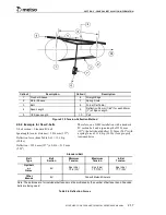
Figure 2-9 Determining Slack Side
2.8.3 Tension-Deflection Method
General method for determining amount of
deflection based on the force applied.
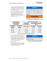
1. Reduce the center distance so that the belts
may be placed over the sheaves and in the
grooves without forcing them over the sides
of the grooves. Arrange the belts so that
both the top and bottom spans have about
the same sag. Apply tension to the belts by
increasing the center distance until the belts
are snug. See Figure 2-9.
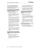
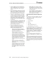
2. Place a straight edge across the top of both
sheaves. See Figure 2-10.
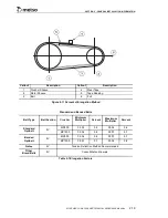
3. Measure the span length.
4. Using a tension device or spring scale at
right angles to the center of the span length,
apply a force to the device or scale great
enough to deflect one of the belts the
equivalent of 0.016 times millimeters of
span length (0.016 times inches of span
length).
Estimate the average deflection for all belts,
not concentrating on either the strongest or
the weakest belt.
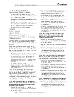
5. The force should approximate the forces in
Table 2-6 for a properly tensioned drive.
These forces are for individual belts and
must be multiplied by the number of belts
per band if banded belts are being used.
Callout
Description
1
Crusher Sheave
2
Motor Sheave
3
Tight Side
4
Slack Side - Note Bow or Sag in Belt
Summary of Contents for MP1000
Page 1: ...Nordberg MP Series Cone Crusher ...
Page 2: ......
Page 4: ......
Page 6: ......
Page 8: ......
Page 64: ...SECTION 0 SAFETY 0 56 MP SERIES CONE CRUSHER TECHNICAL REFERENCE MANUAL ...
Page 66: ......
Page 74: ......
Page 154: ...Countershaft and Countershaft Box Callout Description 1 Countershaft 2 Countershaft box 1 2 ...


