SECTION 2 - GENERAL INSTALLATION INFORMATION
MP SERIES CONE CRUSHER TECHNICAL REFERENCE MANUAL
2-23
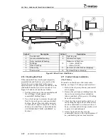
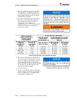
5. Loosen the clamp screw and slide the
bushing onto the countershaft aligning the
sheave key and keyway. If necessary, insert
a wedge (example: screwdriver) into
bushing slit to aid in installation of bushing.
Tighten clamp screw when bushing is tight
against oil flinger.
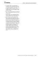
6. Move countershaft in and out to recheck end
float. See CHECKING END FLOAT earlier
in this section.
7. Slide the sheave over the bushing being
careful to keep the bolt holes lined up with
the tapped holes in the bushing flange.
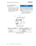
8. Insert the take-up bolts through the bolt
holes and alternately tighten each bolt a
small amount until all bolts are tightened to
a final torque value identified in Table 2-8
based on the size of the sheave bushing. Do
not lubricate the bolt threads or the tapped
holes. When the sheave is finally positioned
a clearance of approximately 10 mm (.375")
should exist between the face of the sheave
hub and the flange of the bushing. No
attempt should be made to take up this
clearance as this clearance assures the
proper fit and grip between sheave bushing
and countershaft. Follow the torque
requirements closely; overtightening the
take-up bolts could cause the sheave to
crack.
Summary of Contents for MP1000
Page 1: ...Nordberg MP Series Cone Crusher ...
Page 2: ......
Page 4: ......
Page 6: ......
Page 8: ......
Page 64: ...SECTION 0 SAFETY 0 56 MP SERIES CONE CRUSHER TECHNICAL REFERENCE MANUAL ...
Page 66: ......
Page 74: ......
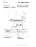
Page 154: ...Countershaft and Countershaft Box Callout Description 1 Countershaft 2 Countershaft box 1 2 ...


