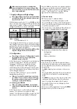
When carrying out repairs, remember that
various components carry mains voltage. After
any work on the set, ensure that the mains isola-
tion is fully established..
1. Supply voltages and high voltage
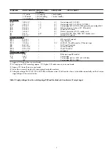
The supply voltages must be measured and adju-
sted with the aid of a DC voltmeter with an accu-
racy of at least 0.3% !
With the beam current set to "0", use
R 1896
on the G
chassis to adjust the voltages D138 and D140 to the
values shown in Table 1. If there are no faults, the high
voltage should then be as shown in the table:
If the voltages D138, D140 are set correctly, the secon-
dary voltage of the power supply unit and the voltages
generated by the line transformer will automatically
have the correct values (see Table 2).
Never attempt to correct the picture width by adju-
sting the voltages D138 or D140 (R 1896) !
2. Configuration
The settings in the menu "Configuration" need to
be changed only if you have replaced the
EEPROM, a tuner or the CRT.
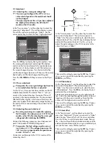
In the "Service menu" (see Section 3), use the blue key
to select "Configuration". The red cursor points to
"Language". Use the cursor control key to select
"Hardware" and then press "
OK
". Depending on
which component you have changed, it may be neces-
sary to set all parameters to new values or only those
for the changed component.
In the lines "CRT" and "Tuner", you can select the
appropriate type from a list.
Take care to select the correct type in each case
(see Table 1). If you select an incorrect CRT type,
the maximum beam current may be exceeded,
resulting in a reduced CRT lifetime.
2.1 Initialising the EEPROM
When you initialise the EEPROM, all stored data
will be lost! The EEPROM is filled with suitable initi-
al values.
In the "Service menu", use the red key to select "Init.
memory". The red cursor now points to "Data
memory". Use the cursor control key or press the "OK"
key to move to the file card labelled "Initialisation".
Press the "
OK
" key to confirm your selection and then
use the cursor control key to move to "Initialise". Press
the "
OK
" key again to confirm this selection and then
use the
- +
key to select "Yes". Press the "
OK
" key
again to start the initialisation procedure
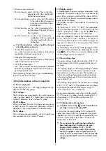
3. Service menu
The "Service menu" is called as follows:
- Switch off the TV set with the main power switch.
- Press and hold any two keys on the control panel of
the TV set until the green LED lights and switch the set
on with the main power switch.
- The service menu is now displayed. The software ver-
sion number is displayed below the Metz logo.
The service menu is divided into three submenus:
- Configuration
- Adjustment
- Memory initialisation
Basic operating procedures
In the service menu, you select the desired submenu
with the key of the same colour on the remote control
unit. You select the various functions with the oval cur-
sor control key
- The
INFO
(Help) key has no function in the service
menu.
- Pressing the
TV
key terminates the service mode and
switches the TV set back to its normal operating
mode.
- The
MENU
key moves you from any menu item to the
next higher level of the menu tree. From the main
menu, it switches the set back to the TV picture.
- Pressing the OK key saves any changes you have
made to the settings.
You can now switch programmes. Pressing the
MENU
key again returns you to the service menu.
☞
☞
☞
☞
☞
2
Table 1: Voltages
*) see also Section 3.1.3
Coloured keys:
call menu
TV: return to TV
picture
Adjustment
Init.memory
TV
-Menü
Configuration
MSM 601 V1.0
D 138
D 140
High
voltage
Chassis
CRT type
A80 EJX 11X429
601 G1 0081
32 KV
140 V
PF84
Um *)
A68 ELR 50X71
601 G1 0073
32 KV
138 V
PA72
800 mV
800 mV
W76 ERF 342X044
601 G9 0083
32 KV
138 V
RF82
800 mV


