3.1 Adjustment
3.1.1 Adjusting the screen-grid voltage Ug2
The screen-grid voltage of the CRT is set to a
value which depends on the model and should
not be changed.
The only exception to this is if you have replaced
the diode split transformer, the CRT, the BV
module or the KS module.
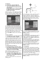
In the "Service menu", use the yellow key to select the
menu item "Adjustment". The set then displays a card
file with the red cursor pointing to "Video". Use the
cursor control key to select the item "Ug2 adjustment"
Press the
OK
key to display the Ug2 test pattern. Turn
the screen-grid adjustment control Ug2 (the bottom
control on the line transformer) fully counterclockwise
and then turn it slowly clockwise until the red bar on
the screen changes to green. Turn the control further
until the bar changes back to red. Then turn the control
back slightly until the bar changes back to green.
Press the
OK
,
MENU
or
TV
key to return to the TV pic-
ture.
3.1.2 Focus adjustment
Prerequisite: the screen grid voltage Ug2 must be
set correctly before the focus is adjusted.
On the TV sets, there are two focus controls on the DF
module (focus block). The control "Focus 1" acts pri-
marily in the vertical direction, the control "Focus 2"
primarily in the horizontal direction. The two controls
affect each other slightly, which means that it may be
necessary to adjust them alternately. Judge the focus at
the centre of the screen and adjust the controls for the
best results.
3.1.3 Adjusting the peak white level
This setting must always be made after replacing
the KS module, the video processor IC 3101, the BV
module, or the CRT, after adjusting the screen-grid
voltage and after initialising the EEPROM.
Connect the following measuring circuit between test
point
◊
63 (anode of D 5580) and ground:
Prerequisite: The Ug2 voltage must be correct
(see Section 3.1.1). The voltage drop across the
100 ( resistor is proportional to the peak beam
current: 100 mV = 1 mA
Connect an oscilloscope to the 100
Ω
resistor of the
measuring circuit.
In the "Service menu", use the yellow key to select the
menu item "Adjustment". The red cursor points to
"Video". Use the cursor control key to select the item
"Peak white level". Press the OK key to display the test
pattern for the peak white level. Use the
- +
key to
adjust the pulse voltage on the 100
Ω
resistor to the
value Um shown in Table 1.
Then save the setting by pressing the
OK
key. If neces-
sary, you can cancel the adjustment by pressing the
MENU
key or
TV
key.
3.1.4 White balance
IIn the "Service menu", use the yellow key to select the
menu item "Adjustment". The red cursor points to
"Video". Use the cursor control key to select the item
"White balance". Press the
OK
key to display the test
pattern for the white balance.
The desired white balance can now be adjusted with
the
- +
key. You can step through the colours in the set-
tings box with the cursor control key. Note that the
colour with the highest value must be set to 31.
Then save the setting by pressing the
OK
key. If neces-
sary, you can cancel the adjustment by pressing the
MENU
key or
TV
key.
3.1.5 Colour offset
In the "Service menu", use the yellow key to select the
menu item "Adjustment". The red cursor points to "Video".
Select the item "Colour offset" with the cursor control key
Press the OK key to switch to adjustment mode. Then use
the
- +
key to achieve the best possible coincidence of the
colour and monochrome pictures, using a suitable test pat-
tern (via the tuner; not an RGB test pattern).
Then save the setting by pressing the
OK
key. If neces-
sary, you can cancel the adjustment by pressing the
MENU
key or
TV
key.
☞
☞
☞
☞
3
Initialise geometry
Geometry adjustment
Video
UG2 adjustment
VCO adjustment
UG2 adjustment
AGC adjustment
SVM factor
SVM phase
Colour offset
White balance
Peak white level
TV
-Menü
Init. memory
Adjustment
Configuration
Initialise geometry
Geometry adjustment
Video
Peak white level 1
VCO adjustment
UG2 adjustment
AGC adjustment
SVM factor
SVM phase
Colour offset
White balance
Peak white level
TV
-Menü
Init. memory
Adjustment
Configuration
100
Ω
Messpunkt
2,2 n
5,6 V
22 k
12 V
: select
menu item
: select
menu item


