3.1.6 SVM factor and SVM phase
The menu items "SVM factor" and "SVM phase" are
automatically adjusted after initialisation of the
EEPROM.
3.1.7 VCO adjustment
The VCO adjustment must always be carried out after
replacing the quartz crystal Q5901 or the digital colour
decoder IC 5901 and after initialising the EEPROM..
A suitable test pattern (not RGB) should be used for
adjustment of the VCO (the voltage-controlled oscilla-
tor which is important for the capture range of the
colour carrier frequency). The colour carrier of the test
pattern should be as accurate as possible.
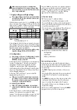
In the "Service menu", use the yellow key to select the
menu item "Adjustment". With the cursor control key,
choose the option "VCO adjustment". Press the
OK
key
to switch to adjustment mode. Then use the
- +
key to
select "No", "Yes" or "Default". Selecting "Yes" starts
adjustment of the VCO with the colour carrier of the
displayed test pattern. If no suitable test pattern is avai-
lable, you can set the VCO to a default value by selec-
ting "Default".
3.2 Colour purity
(on model Spectral-84 MF 84 TH 89 only)
On the model
Spectral-84 MF 84 TH 89
, the service
menu
VCO adjustment
contains the additional item
"
Colour purity
".
With this menu item, it is possible to adjust the colour
purity in all four corners of the screen with the aid of a
setting menu. A red screen is displayed to facilitate this
adjustment. Depending on the installation location and
any existing colour inpurities, it may be necessary to
change the factory setting.
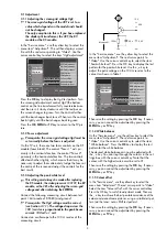
Adjust the colour purity, while viewing the red screen
to detect any impurities. The four adjustments top left,
top right, bottom left and bottom right (these are also
displayed as text on the screen) may affect each other
slightly.
In the menu, you can select the four corners with the
P+
and
P–
keys and adjust the values with the
+
and
–
keys.
3.3 Picture geometry (no internal test pattern possible)
Selecting factory or table values:
Explanation:
Basic geometry values: The current picture geometry
settings. If the picture geometry
is changed, the new values are
stored here.
Factory geometry values: The picture geometry settings
which were made in the fac-
tory.
Table values: The picture geometry data stored in the
computer programme memory (flash
memory, IC3665), sorted by CRT diago-
nal dimension. These are identical for all
TV sets with a CRT of the same diagonal
dimension.
In the "Service menu", use the yellow key to select the
menu item "Adjustment". With the cursor control key,
first call the item "Initialise geometry" and then "Fac-
tory geometry values" or "Table values". Press the OK
key to switch to the lower settings box. The
- +
key now
permits you to select either "yes" or "no". Then save
the setting by pressing the
OK
key.
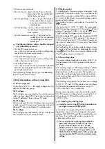
Adjusting the picture tube:
If you have replaced the EEPROM (IC 2250), then:
Open the "Service menu" and use the blue key to sel-
ect "Configuration". The red cursor points to "Langua-
ge". Use the cursor control key to select "Hardware"
and press the
OK
key to confirm this selection. Then
use the cursor control key to select the menu item
"CRT" and press the OK key for confirmation. You can
now choose the CRT type with the
- +
key. Finally, con-
firm this selection by pressing the
OK
key.
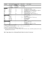
Adjustment the picture geometry:
The picture geometry may be adjusted only with
a test pattern with a vertical frequency of 50 Hz!
In the "Service menu", use the yellow key to select the
menu item "Adjustment". Use the cursor control key to
select the item "Geometry adjustment" and press the
OK key to confirm this selection. Then use the cursor
control key to select the desired geometry correction
and confirm this by pressing the
OK
key.
You can now adjust the selected value with the
- +
key.
Save the changed setting by pressing the
OK
key. By
repeating the above steps, you can adjust any or all of
the following geometry settings sequentially:
• Vertical picture position
• Picture amplitude: adjust for an overscan of 3%.
• Horizontal picture position
• Picture width
• East-West parabola
• East-West trapezoid
• Corner correction, top
• Corner correction, bottom
☞
4
Initialise geometry
Geometry adjustment
Video
Top left
0 Top right
0
Bottom left 0 Bottom right 0
: select
menu item
Colour purity
VCO adjustment
UG2 adjustment
SVM factor
SVM phase
Colour offset
White balance
Peak white level
TV
-Menü
Init. memory
Adjustment
Configuration


