3. Installation
page 18
ELC PE22B-PE35B V1.0-05.19-GB
Subject to technical alterations
3.5.1.
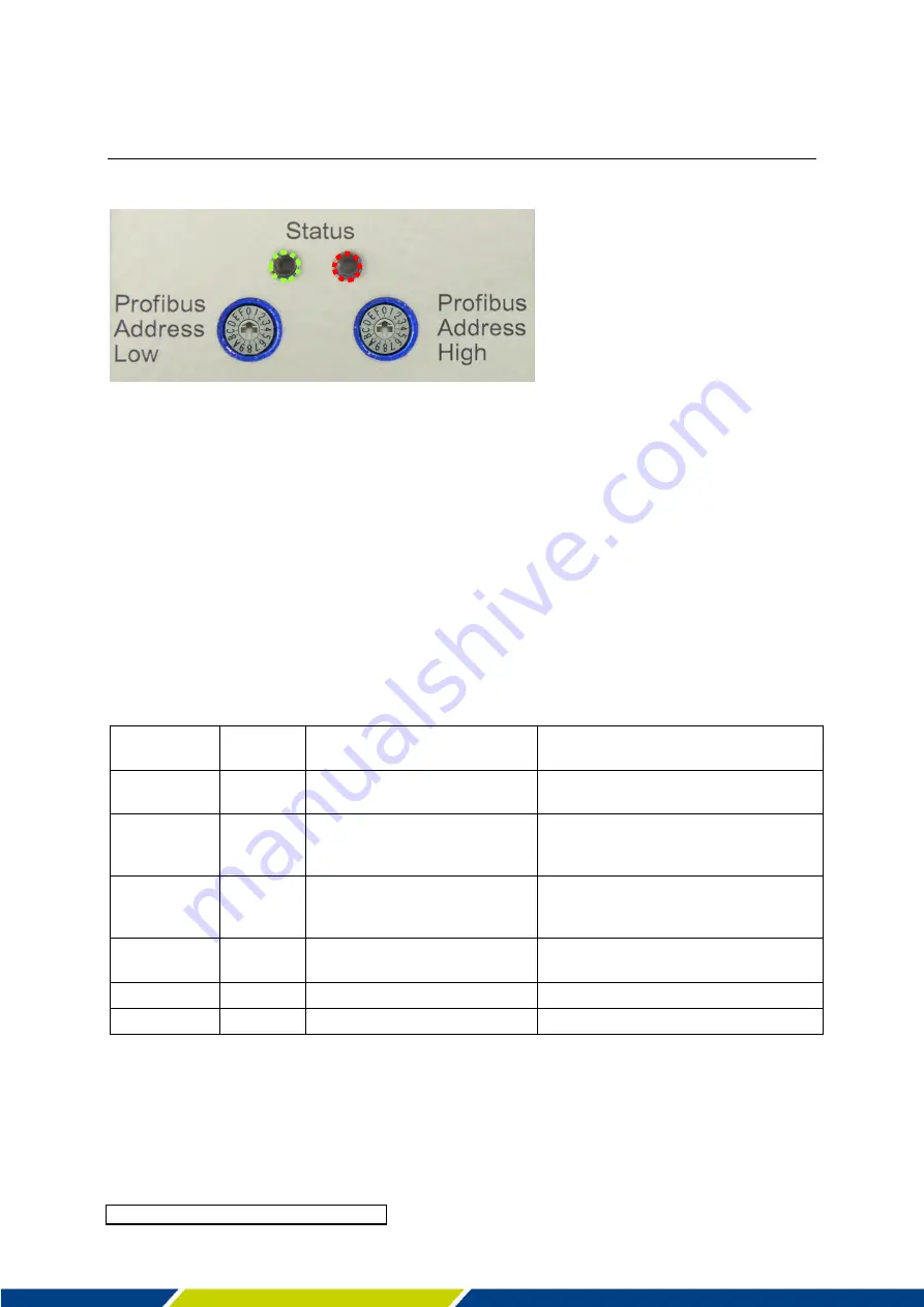
Setting up the PROFIBUS address
Fig. 7:
LED status (green left, red right) and rotary coding switch for low and high nibble
The PROFIBUS address must be set using the rotary coding switches.
The address space extends from 01_hex to 7D_hex (corresponding to 1 to 125), whereby low
and high nibble are allocated according to Fig. 7. Each address may be used only once per
installation.
The address is adopted when current is applied to the ELC (paragraph 4.2). If the appliance is
already under power supply, it must first be disconnected.
3.5.2.
Checking the PROFIBUS connection
The Status-LED (Fig. 7)
may be used to check the successful connection of ELC and Master
and furthermore the existence of an error (ELC not ready for operation):
LED green
(left)
LED red
(right)
Status
Corrective action
on
off
ELC ready for operation,
PROFIBUS-connection ok
blinking
off
ELC ready for operation, no
PROFIBUS-connection
Check plug contact, bus termination (see
paragraph 3.3.3), check address and
panel-programming.
on
blinking
ELC not ready for operation,
PROFIBUS-connection ok
The error cause detected by the ELC may
be read out in the Error Register (see
paragraph 5.4.1)
blinking
blinking
ELC not ready for operation, no
PROFIBUS-connection
Detach ELC from mains and restart.
off
blinking
Internal error.
Detach ELC from mains and restart.
off
off
Internal error or no supply.
Check power supply


