background image


© Meunier Technologies Inc. 2022 - All rights reserved 


Safety 

General 

Carefully read this manual before installing, starting up and servicing the DICE

TM

 dosing 

module. 

 
Warning  notes  must  be  strictly  followed  in  order  to 
avoid injuries and damages.  


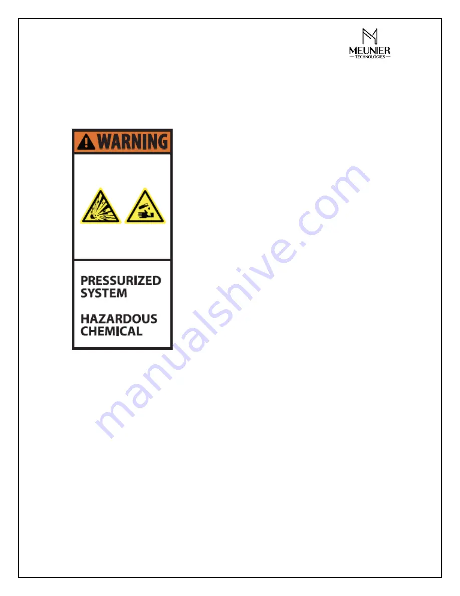
The  module  is  internally  pressurized  and  can 

cause injuries if not handled correctly.  


The fluids* used  in the dosing  module  or  in  the 

cleaning process may be hazardous.  


The  following  minimum  personal  protective 

equipment  should  be  used  near  the  dosing  module: 
protective gloves, glasses and clothing.  


Always  refer  to  the  MSDS  for  all  safety 

instructions related to the fluids* used. 


Turn  off  electrical  power,  depressurize  system, 

release both regulating valves (back pressure valve and 
pressure  relief  valve),  and  vent  fluids*  to  a  safe  area 
before servicing the DICE

TM

 dosing module. 


Always  flush  all  fluids*  prior  to  module 

maintenance. 
 
Refer  to  technical  specifications  for  the  maximum 
operating flow, pressure and operating temperature. 

 
Modifying  the  DICE

TM

  module,  installing  non-factory  parts  or  not  following  the 

maintenance procedure listed in the present manual may cause injuries, affect  product 
performance, be hazardous and void existing limited warranties. 
 
*Note: Fluids include: chemicals, polymer solutions, cleaning solutions, water, etc. 


Summary of Contents for DICE ES

Page 1: ...ogies Inc 2022 All rights reserved 1 DICETM Dosing Module Model ES Installation Operation and Maintenance Manual Date 2022 02 02 Version V1E Meunier Technologies Inc meuniertechnologie com info meuniertechnologies com ...

Page 2: ... 8 Connection reference numbers 8 Model Number nomenclature 9 Parts List 10 Installation 11 Mounting 11 Upper bracket 11 Lower bracket 12 Pump installation 13 Typical Installation 14 P ID 15 Operation 16 Start up 16 Setup and adjustment 16 Normal Operation 18 System depressurising 18 Maintenance 19 Disassembly and Assembly 19 Pressure relief and back pressure valve 19 Pressure indicator and isolat...

Page 3: ... Meunier Technologies Inc 2022 All rights reserved 3 Cleaning 22 Pressure relief and back pressure valve 22 Pressure indicator and isolator 22 Spare Parts 22 Troubleshooting 23 ...

Page 4: ...hing Always refer to the MSDS for all safety instructions related to the fluids used Turn off electrical power depressurize system release both regulating valves back pressure valve and pressure relief valve and vent fluids to a safe area before servicing the DICETM dosing module Always flush all fluids prior to module maintenance Refer to technical specifications for the maximum operating flow pr...

Page 5: ... and Maintenance manual and the purchased spare parts Storage and Handling The DICETM dosing module must be stored indoors inside its cardboard box at a temperature of between 5 C to 40 C and with a relative humidity level under 80 The DICETM dosing module must be stored without any pre set pressure on the back pressure valve and pressure relief valve Excessive stacking of packages may cause damag...

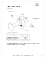
Page 6: ...cal Specifications Maximum pressure psi DIXX1 DIXX2 150 250 Ambient operating temperature C 5 40 Liquid operating temperature C 5 40 Storage Temperature C 5 40 The dosing module should not be used with fluid containing slurry or fluid which could crystallize or which may have already crystallized ...

Page 7: ... Meunier Technologies Inc 2022 All rights reserved 7 Dimensions DIMENSIONS mm in Size A B C 1 4 ES DIE1X 254 3 10 01 123 2 4 85 204 1 8 03 ...

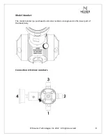
Page 8: ... Meunier Technologies Inc 2022 All rights reserved 8 Model Number The model number as purchased and serial number are engraved on the lower part of the block body Connection reference numbers ...

Page 9: ...te Other materials can be supplied upon request Options will be listed at the end of the Model Number in the option section 1 2 3 4 1 1 1 Z XXX DICE DI Configuration ES E Size in 1 4 1 Pressure 150 psi 1 250 psi 2 PVC V PVDF D PVC V PVDF D O ring Material VITON I EPDM E Diaph Material VITON I EPDM E Connections 1 Z No Connector W Option 1 2 MNPT Hose LMI M V I I Parts Material Isolator pressure Ga...

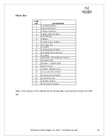
Page 10: ...OCKET HEAD SCREW 8 CAP HEX NUT 9 WASHER 10 SOCKET HEAD SCREW 11 COUNTER LOCK HEX NUT 12 WASHER 13 ISOLATOR AND PRESSURE GAUGE 14 CONNECTOR 15 O RING CONNECTOR 16 BLEED VALVE 17 O RING BLEED VALVE 18 WALL MOUNT SUPPORT 19 BASE MOUNT SUPPORT 20 MOUNTING TAB 21 SUPPORT SCREW 22 BASE MOUNT SCREW Refer to the figures in the Installation and Disassembly and Assembly sections for PART NO ...

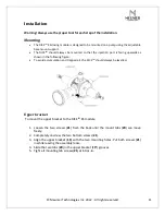
Page 11: ... upwards as shown in the following figure To avoid accumulation and trapped air the DICETM should always be levelled Upper bracket To mount the upper bracket to the DICETM ES module 1 Loosen the two screws 21 from the back until the mount tabs 20 can move freely 2 Completely unscrew the two bottom screws 21 3 Align the upper bracket 19 with the two mounting holes Put both screws 21 in while leavin...

Page 12: ... 1 Fix the bottom part of the bracket 19 by using screws in the dedicated holes 2 Make sure that the suction line clearance hole is not blocked so that the pump suction line can go through 3 Remove the 4 screws 22 from the bracket 4 Attach the DICETM ES module and upper bracket to the lower bracket using four screws 22 ...

Page 13: ...t bottom part 19 by using the pump mounting holes 2 Make sure that the suction line clearance hole of the lower bracket is aligned with the pump suction port 3 Adjust the DICETM ES by loosen the screws 22 and sliding the upper bracket The module and the pump should be separate about 3 inches 75mm from each other 4 Tight all mounting screws 22 to 100 oz in ...

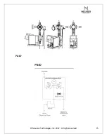
Page 14: ...s Inc 2022 All rights reserved 14 Typical Installation The following figure can be used as a typical installation of the DICETM ES dosing module on a dosing pump Note Never use a pipe wrench for dosing module installation ...

Page 15: ... Meunier Technologies Inc 2022 All rights reserved 15 P ID ...

Page 16: ...d Maintenance Manual should be available at all times Setup and adjustment The pressure relief and back pressure valve needs to be adjusted prior to system operation Pump priming In order to help the pump priming at start up you can unscrew the Bleed Valve 16 until the fluid start flowing through the evaluation port Once the pump is primed screw the Bleed Valve 16 back in place hand tightened no t...

Page 17: ...er nut 11 See note 5 Stop the pump and slowly open the bleed valve to release the system pressure Proceed with the back pressure valve adjustment Back pressure valve adjustment 1 Start the pump and wait until pressure is build up 2 Use the adjustment screw 10 to obtain the desired pressure set point by initially unscrewing the back pressure adjustment screw 10 3 Once the desired set pressure is ob...

Page 18: ...rew the Bleed Valve 16 until the fluid pressure is released through the evaluation port The pressure indicator reading should drop all the way to 0 psi The pressure upstream of the back pressure valve should be release and maintenance can now be carried out on the dosing pump Once the pump is back in place proceed with the pump priming There can be a residual pressure up to 5 10psi inside the pres...

Page 19: ...ief and back pressure valve 1 Using a 6mm Allen key loosen and remove the adjustment screw 10 along with the counter nut 11 and washer 12 2 Loosen and remove the four regulating valve mounting bolts washers and nuts 7 8 9 with a 4 mm Allen key and a 8mm socket wrench 3 Remove the regulating valve body 2 4 Remove the spring assembly spring 6 top seat 3 and bottom seat 4 5 Remove the diaphragm 6 fro...

Page 20: ...in lb Make sure the regulating valve body 2 is properly seated on the block 1 by ensuring no gap is present between the two parts using a filler gauge on four different points The following tools are required Adjustment screw 10 6 mm hex bit wrench Mounting screws 18 4 mm hex bit wrench Torque wrench ...

Page 21: ...re indicator assembly 13 should be disassembled from the block 1 and shipped to the supplier with the RMA form The re installation of the isolator should be done manually hand tightened no tools should be used for tightening Note The pressure indicator and isolator assembly shall not be disassembled on site The isolator filling is made by our technician using specialized tools prior to shipment No...

Page 22: ...compatible with the dosed chemical and system materials Refer to your chemical supplier Pressure relief and back pressure valve The DICETM back pressure and pressure relief valve diaphragms should be fully inspected at least every three 3 years If the diaphragm shows signs of wear it should be replaced Follow the disassembly and assembly procedure indicated in the above section CAUTION Strictly fo...

Page 23: ...gm and the block Tighten the 4 mounting screws to 35lb in Adjustment screw not working Regulating valve spring failure Spring replacement Tighten the pressure gauge NPT connection on the isolator Ruptured diaphragm chemical attacked pressure indicator connection Bleeding screw o ring failure Ruptured diaphragm Back Pressure and Pressure Relief Valve Leaking from the valve block interface Pressure ...

Reviews: