background image

1

2

3

32

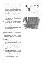
Adjusting the adjustable back

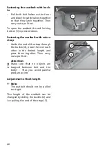
1.  Pull off the rear part of the cush-

ion.

2. Span the spanning straps tightly 

over the small of the back and 
lumbar spine in order to give maxi-
mum support.

3.  Adjust the remaining straps to the 

form of the back.

4.  Afterwards loosen the front part 

of the cushion and align it with the 
spanning straps.

 In doing so the user should lean 

forward. If necessary ask an aid to 
help out!

5. The extended back strap is at-

tached to the adjustable seat strap 
with velcro straps (3).

Place the back cushion

The back cushion (1) is to be folded 
over in the centre between the two 
horizontal seams 180° around the up-
per spanning straps (2). – This creates 
a soft upper edge.

  Note:

  When the user leans against the 

front cushion again, pay attention 
that:

 The pressure of the back must be 

spread evenly throughout the back 
cover.

 A complete hand should fi t in be-

tween the cover and back at the 
upper edge of the back cover.

 The head of the user must be held 

at balance by the back cover.

Summary of Contents for CLOU 9.500

Page 1: ...GB We move people OPERATING MANUAL CLOU MODEL 9 500 ...

Page 2: ...g brake 11 Selection lever 12 Locking the brake 12 Releasing the brake 12 Drive push mode 13 Selecting the push mode 13 Selecting the motor mode 13 Selecting the operation 14 Pre operation checks 15 Charging procedure 16 Positioning the operating module 17 Function description 17 Horizontal adjustment 17 Vertical adjustment 17 Remove the operating module 17 Fitting of the operating module 17 Turni...

Page 3: ...djusting the height of the arm supports 28 Adjusting the clothes guard 28 Height stopper Memory effect 29 Depth adjustment of the arm support cushions 29 Back support 30 Standard back support 30 Detaching the standard back support 30 Attaching the standard back support 30 Adjustable back 31 Adjusting the angle of the back support 33 Seat 34 Seat cushion 34 Removing the seat strap 34 Inserting the ...

Page 4: ... height of the footplate 40 Lifting the height adjustable leg supports 41 Lowering the height adjustable leg supports 41 Adjusting the depth of the calf pads 42 Adjusting the height of the calf pads 42 Stump support 42 Swivelling away removing the leg stump support 42 Attaching the leg stump support 43 Adjusting the height of the stump support 43 Positioning the calf plate 43 Stick in support whee...

Page 5: ...51 Adjusting the rear view mirror 51 Service 52 Maintenance 52 Inspection 52 Maintenance instructions 53 List of annual maintenance work 55 Fault correction 56 Battery charger 57 Wheel change 58 Disassembly of the drive wheels 58 Assembly of the drive wheels 58 Disassembly of the steering wheels 59 Assembly of the steering wheels 59 Fuses 60 Replacing the fuses 60 Lighting 61 Adjusting the headlig...

Page 6: ... parameter 67 Standard programming 67 Technical data 68 Kilometric performance 68 Hill climbing ability 68 Fuses 69 Lighting 69 Tools 70 Tightening torque for screwed connections 70 Model 9 500 71 Meaning of the labels on the wheelchair 75 Inspection certificate 76 Guarantee 78 ...

Page 7: ...t therefore be learned This manual is to help you get accus tomed to the handling of the electric wheelchair as well as to prevent acci dents Note Please note that the illustrated equipment variants can deviate from your model Attention Read and observe the following documentation belonging to the electric wheelchair before first use this operating manual the operating manual Operating modules VR2...

Page 8: ...n of all relevant safety instructions ready for operation and adjusted to your needs Note The tools required for adjustments and maintenance is listed under chapter Technical Data SPECIFICATIONS The electric wheelchair is an environ ment friendly electric vehicle It was developed to extend the mobility of persons with health related or age re lated restrictions USE The electric wheelchair with att...

Page 9: ...mponents and operating devices of the electric wheelchair Push mode Drive mode Pos Description 1 Back support 2 Operating module 3 Seat cushion 4 Leg support 5 Footplate 6 Calf strap 7 Selection lever drive push mode 8 Arm support 9 Steering wheel 10 Drive wheel 11 Support castor 12 Push bar ...

Page 10: ...k movements driving and steering lever while driv ing as well as the pre adjusted maxi mum final speed of your electronic wheelchair Functional checks The functions and safety of the elec tric wheelchair must be checked be fore the start of each journey For this observe chapter Inspec tions before starting to drive in the Operating manual of the Op erating modules VR2 Tips for accident prevention ...

Page 11: ...otted braking of the wheelchair slowly guide the joystick back to the centre position zero setting The wheelchair stops in shortest distance after releasing the joy sticks Parking brake The parking brakes only work when the selection lever is in the drive mode position They disengage auto matically when the wheelchair starts off They are disengaged manually by moving the selection lever to the pus...

Page 12: ...e it immediately to your specialist workshop for repair Releasing the brake Activate the locking sleeve 2 on the selection lever and swivel the selec tion lever back as far as possible 3 Attention Only transfer to and from the elec tric wheelchair when the wheel chair is switched off and the selec tion lever has been placed into the drive position An unintentional movement of the joysticks driving...

Page 13: ...ng to the drive mode Therefore do not switch to the push mode on gradi ents Selecting the push mode First switch off the operating module because the pushing will otherwise be made difficult by the electric system Afterwards activate the locking sleeve 2 on the selection lever and swivel the selection lever back as far as pos sible 3 Attention Do not switch the selection lever to push mode while d...

Page 14: ...rge the drive batteries via the operating module before the first journey 1 Shift to drive mode Move the drive motors to the drive mode position Push the selection lever to the front 1 until it audibly latches 2 Check the tight seat of the bat tery fuse Blade type fuse The flat fuses 2 for the battery cur rent must sit securely in the fuse hold ers of the respective battery cover 3 ...

Page 15: ...key on the key field of the control panel Note Only actuate the joystick 4 after the self test of the electronics has been completed Key lock function The key lock function enables you to secure the wheelchair against unauthorised use Observe user manual Operating module VR2 chapter Key func tion Pre operation checks Before starting to drive the following should be checked the battery charge level...

Page 16: ...charging socket Dan ger of short circuit 3 Switch on the battery charger re spectively plug the mains plug of the battery charger into a conven ient mains socket The battery is now charging The charging procedure will only run with intact battery fuses 2 A full charging of the drive batteries takes approximately 8 hours 4 Disconnect the battery charger from the mains socket at the end of the charg...

Page 17: ...operating module into the desired position In doing so carefully guide the cable and retighten the clamping screw secure ly Vertical adjustment With the optional height adjustable operating module adapter the op erating module can be adjusted in height Slacken the clamping lever 2 whilst holding the control unit move the op erating module into the desired posi tion and then retighten the clamping ...

Page 18: ...ove the operating module more easily For regular drive mode the operating module can be swivelled back toward the front 1 until it engages back into the magnetic lock Note The power of the magnets 3 can be reduced for example with tape on top of the magnets for easier swivelling of the operating mod ule Should the operating module be positioned too close to the arm support move it forward before s...

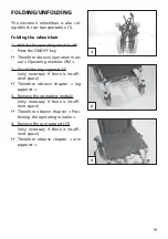
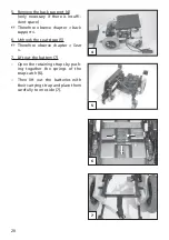
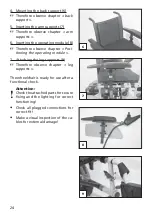
Page 19: ...tion man ual Operating modules VR2 2 Lift off the leg supports 2 only necessary if there is insuffi cient space Therefore observe chapter leg supports 3 Remove the operating module only necessary if there is insuffi cient space Therefore observe chapter Posi tioning the operating module 4 Remove the arm supports 3 only necessary if there is insuffi cient space Therefore observe chapter arm support...

Page 20: ...erefore observe chapter back support 6 Unhook the seat strap 5 Therefore observe chapter Seat 7 Lift out the battery 7 Open the retaining straps by push ing together the springs of the snap catch 6 Then lift out the batteries with their carrying strap and place them carefully to one side 7 ...

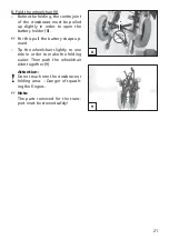
Page 21: ...e battery holder 8 For this pull the battery straps up ward Tip the wheelchair slightly to one side in order to make the folding easier Then push the wheelchair sides together 9 Attention Do not reach into the crossbrace or folding area Danger of squash ing the fingers Note The parts removed for the trans port must be stowed safely ...

Page 22: ... Unfold the wheelchair 2 Attention Do not reach into the crossbrace or folding area Danger of squash ing the fingers Tip the wheelchair slightly to one side in order to make the unfold ing easier At the side resting on the floor press the seat tube down to the end stop 1 Note You may need to press down both seat tubes with the hands in order to do this Then press the crossbrace joint of the batter...

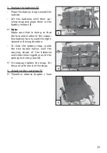
Page 23: ...g so that the fuse and marker of the respec tive battery face toward the right viewed in driving direction To close the battery strap guide the two buckle halves over the carrying straps of the batteries and slide them together until the springs lock into place 4 If necessary tighten the strap For this pull at the end of the strap 3 Attaching the seat strap 5 Therefore observe chapter Seat ...

Page 24: ...Therefore observe chapter Posi tioning the operating module 7 Attaching the leg supports 9 Therefore observe chapter leg supports The wheelchair is ready for use after a functional check Attention Check the attached parts for secure fixing and the lighting for correct functioning Check all plugged connections for correct fit Make a visual inspection of the ca bles for external damage ...

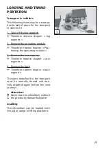
Page 25: ...fore observe chapter Posi tioning the operating module 3 Remove the arm supports Therefore observe chapter arm supports 4 Remove the back Therefore observe chapter back support The parts detached for the transport must be carefully stowed and care fully attached again before the next journey Attention No not use the wheelchair without the previously dismantled parts Loading The wheelchair can be l...

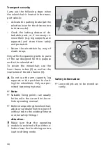
Page 26: ...and to the wheelchair To secure the wheelchair use the front frame tubes 2 as well as the rear tubes of the side frames 3 Do not use the arm supports leg supports or the push bar for lash ing the wheelchair Only use per mitted fastening material Note Suitable fixing points can usually be found in the car and in the ve hicle operating manual Beforetransportingthewheelchair ask your car dealer how t...

Page 27: ...pport Slacken the clamping screw 1 and pull off the arm support upwards Note The operating module must be re moved first if the arm support on the control side is to be detached To remove the control unit slacken the clamping screw 2 Note Carefully route the cable when do ing this Inserting the arm support Insert the arm support from the top up to the desired height into the guide tube Then fasten...

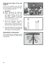
Page 28: ...ling down with your hand Danger of jamming with disassembled or too loosely screwed clamping screw 3 During the adjustment the maxi mum arm support height is reached when a mark becomes vis ible above the receptacle tube 4 Ensure the tight fit of the clamping screw 3 in order to prevent the arm support from sliding down Adjusting the clothes guard After loosening the clamping screws 5 slide the re...

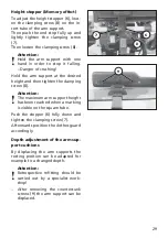
Page 29: ...desired height and then tighten the clamping screw 8 Attention The maximum arm support height has been reached when a marking is visible on the square tube Push the stopper 6 fully down and tighten the clamping screw 7 Afterwards position the clothes guard accordingly Depth adjustment of the arm sup port cushions By displacing the arm supports the resting position can be adapted for example to a c...

Page 30: ... port Screw the attachment screws far out on both sides in order to remove the standard back support 3 Then pull the standard back support out toward the top 2 Attaching the standard back sup port For attachment insert the back sup port tubes from the top as far as possi ble into the respective guide tube 4 Then retighten the attachment screws 5 on both sides ...

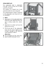
Page 31: ...hed to the adjustable seat strap with vel cro straps 4 Note Adjustment of the adjustable back strap 2 is best achieved while the user is sitting inside the wheel chair Adjustment is carried out from the bottom to the top The lower part of the adjustable back should remain slightly loose so that it adapts to the buttocks when bending forward Attention The overlapping of the Velcro fas tener has to ...

Page 32: ...an aid to help out 5 The extended back strap is at tached to the adjustable seat strap with velcro straps 3 Place the back cushion The back cushion 1 is to be folded over in the centre between the two horizontal seams 180 around the up per spanning straps 2 This creates a soft upper edge Note When the user leans against the front cushion again pay attention that The pressure of the back must be sp...

Page 33: ...prings Note Before activating the release lever 2 hold on to the pushing handles in order to prevent the back sup port from unintentionally snap ping up Activate both release levers 2 si multaneously and adjust the back tubes parallel 3 Let go of both release levers 2 si multaneously The back support is set again Note Suitable tooling is required to re move the back support with actua tor ...

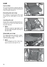
Page 34: ...oked on one side 2 Inserting the seat Stretch the seat strap and press the re taining pins of the seat strap bar into the seat tube 3 Note The pins must be depressed until the seat strap ledge lies securely on the seat tube Adjustable seat strap The adjustable seat strap 4 is adjust able through a velcro strap the so called spanning straps Note The overlapping of the Velcro fas tener has to be at ...

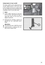
Page 35: ...istance after slackening the clamping screw 1 on both sides Note A seat width reduction of less than 43 cm can be achieved through a right left switch of the two arm support cushions Retrospective refitting should be carried out by a specialist work shop Attention The maximum seat width has been reached when a marking 2 is vis ible on the square tube ...

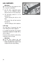
Page 36: ... floor to remove the calf belt and the leg support before folding up the footplates Calf strap The calf strap 1 prevents the feet from sliding off of the footplates It is guided around the leg support tube 2 and adjusted in length with a velcro fastener Removal of the calf belt is achieved by opening the velcro straps Attention Do not drive without the calf belt The leg strap is omitted for height...

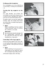
Page 37: ... swivel the corresponding leg sup port outward Note Before swivelling the leg support outward inward loosen or remove the calf belt on one side Attention Swivelled away leg stump supports are automatically unlocked and can easily fall off Note this when handling e g transport Swivelling in the leg supports Swivel the leg support from the side or just replaced leg support inward as far as possible ...

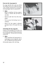
Page 38: ... one side Remove both feet from the foot plates Pull or press the locking lever in ward 2 Swivel the leg support sideways and take them off toward the top 1 Attaching the leg supports Hang in the leg supports from the top at the side then swivel them inward as far as possible Then press the locking device 2 Note After swivelling the leg support in ward again do not forget to check the correspondin...

Page 39: ...re it with the clamping screw Adjusting the angle adjustable foot plate After loosening the clamping screw 2 pull out the dovetail connection and adjust the angle of the footplates Attention Ensure that the footplate has suf ficient ground clearance Afterwards retighten the clamping screw 2 Note In doing so the teeth of the angle adjustment must join again ...

Page 40: ...he leg supports from the top at the side then swivel them inward as far as possible Then press the locking device 1 Note After swivelling the leg support in ward again do not forget to check the corresponding locking device Adjusting the height of the foot plate Loosen the clamping screw 2 to ad just the height of the foot plate Telescope the foot plate to the desired height and then retighten the...

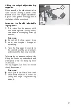
Page 41: ...st folding down and press the clamping lever 3 forward Attention Do not let the leg support drop on its own weight Danger of squashing 2 Have the leg support lowered to the desired level by an attendant and release the clamping lever 3 To lower the leg support relieve it by lifting the lower leg attendant and afterwards press the clamping lever 1 forward The leg support can now be moved slowly dow...

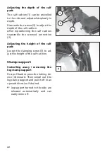
Page 42: ... reassemble the screwed connection 2 Adjusting the height of the calf pads Loosen the clamping screw 3 to ad just the height of the calf cushion Stump support Swivelling away removing the leg stump support First pull back or press the locking de vice 4 inward Then swivel out the leg stump support and pull it off in an upward direction if desired leg support turned to the side are released automati...

Page 43: ...cking device Adjusting the height of the stump support You raise the stump support by simply pulling it up to the desired height 2 For lowering hold on to the leg stump support and press the clamping lever 3 forward Secure the leg stump support against unintentional lowering Positioning the calf plate Swivel the calf plate slightly outwards and then move it to the desired posi tion Check the locki...

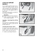
Page 44: ... 3 or pulled off for transport or storage Attention Support castors do not provide suf ficient protection against tipping over in certain situations Inserting removing the anti tip castors First press the corresponding spring button 2 the insert or pull out the anti tip castor 3 Inserting the anti tip castors To attach the anti tip castor push it inward or pull it out until the spring button visib...

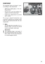
Page 45: ...ous adjustment to suit the user s needs The strap is placed behind the rear seat tube receptacle around the frame tube 1 and reattached with the slid ing buckle Note The retrospective assembly of a re taining strap is only to be carried out by a specialist workshop Attention The retaining strap is not part of the retaining system for the wheel chair and or user during transport in a handicapped ve...

Page 46: ...t with velcro strap Guide the end of the strap through the buckle 4 place the over each other in the desired length and press them together Then carry out a pull test Attention Make sure that no objects are trapped between belt and the body Thus you avoid painful pressure points Adjustment of belt length Note The seatbelt should not be pulled too tight The length of the seatbelt can be changed by ...

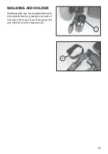
Page 47: ...1 2 47 WALKING AID HOLDER Walking aids can be transported with the wheelchair by placing one end of the aid in the cup 1 and securing the aid with the Velcro fastener 2 ...

Page 48: ...ed suitable for the obstacle height The step climber will make contact with the obstacle first and the impe tus will lift both swivel wheels over the step Attention An increased danger of tipping over exists in the following situa tions when crossing an obstacle with the step climber A seat inclination adjustment Driving with angle adjusted back support Driving on a rising falling gradient especia...

Page 49: ...ightly for wards and then pull it out of the left holder Attaching the step climber Insert the fixed pin 3 of the step climber into the left holder Then pull the ball knob 1 to the mid dle of the wheelchair in order to pull in the movable pin Align the pin with the right holder and then press the ball knob 1 out wards until the pin protrudes into the holder 4 Then pull up the ball knob and turn it...

Page 50: ...e operating module before position adjustment This prevents an unwanted movement of the wheelchair Height adjustment Hold the operating module and then slacken the clamping screw 1 Move the operating module into the desired position and retighten the clamping screw Angle adjustment Hold the operating module and then slacken the clamping screw 2 Swivel the operating module into the desired position...

Page 51: ...orward Note Carefully place the rear view mir ror down and protect the mirror glass from strain or other objects The rear view mirror is to be kept clean at all times Use common glass cleanser to clean the mirror For this the users instructions of the manufacturer are to be observed Attaching the rear view mirror Reinsert the rear view mirror for drive mode Tighten the clamping screw 2 Adjusting t...

Page 52: ...ent of the wheelchair The main fuse must additionally be removed when working on the electrical system Inspection For safety reasons and to prevent ac cidents which can result from wear not detected in good time an annual inspection is necessary in the case of normal operating conditions This is to be carried out in accordance with the service manual Have this work carried out by a spe cialist wor...

Page 53: ... le ver drive push mode to drive mode Lighting Especially before driving in the dark Replacing defective fila ment bulbs view chapter Maintenance Light ing Every 2 weeks depending on distance covered Check air pressure of the tyres Full tyre pressure steer ing wheel 2 5 bar 35 psi Full tyre pressure drive wheel 2 5 bar 35 psi Lighting and direc tion indicating sys tem Test for faultless opera tion...

Page 54: ...teries No maintenance depending on distance covered Check tyre profile Minimum tread 1 mm If the tyre profile is worn down or if the tyre is damaged consult a spe cialist workshop for re pairs Every 6 months depending on frequen cy of use Check Cleanness General condition See Care See Repairs Do it yourself or with the aid of a helper Manufacturer recom mendation Every 12 months depending on frequ...

Page 55: ...wden cables for damages Chassis Check the fastening of the steering and drive wheels Check the tyre condition and tyre pressure Check the condition functioning and smooth operation of the steering wheel suspension Brakes Check the automatic brake system for correct functioning Max braking distance at 6 km h 1 m at 8 km h 1 5 m at 10 km h 2 1 m Electrical system Clean and service drive batteries co...

Page 56: ...to place Battery fuse is defective or not correctly inserted Replace defective fuse or clean contacts and insert correctly Malfunction in the elec tronics Have the fault corrected by an authorised work shop Push mode Selection lever in driving mode position Lighting not active Filament bulb defective Lighting electronic de fective Replace defective fila ment bulb Let it be repaired or re placed by...

Page 57: ...charging voltage 28 5 V For sealed batteries up to 40 Ah 5 h 50 Ah 20 h Charging current 6 A For open sealed drive batteries from 40 Ah 5 h 50 Ah 20 h Charging current 8 A Pin assignment of the charging plug B Pin 1 24V Conduit red Pin 2 minus Conduit black Pin 3 minus Bridge on Pin 2 view arrow Therefore observe the operating manual of the charger Pin assignment of the charging socket C Pin 1 24V...

Page 58: ...eelchair from tipping over and secure it to prevent an un wanted movement or tipping over Always change tyres in pairs Because differently worn tyres can impair the straight on travel of the wheelchair Disassembly of the drive wheels For this remove the protective cap 1 first then unscrew the wheel attach ment nut 1 and pull off the wheel Assembly of the drive wheels After attaching the drive whee...

Page 59: ...of injury Note Take note of the arrangement of all sleeves and washers used Assembly of the steering wheels After inserting the steering wheel the wheel axle 2 is to be reassembled Note The torque in Nm can be found in the Technical data Changing the tyres The tyre is to be levered off of the rim with suitable tooling assembly lever Attention Fully de inflate the tyres for a tyre change Note The a...

Page 60: ...ive mode position to prevent the wheelchair from moving Switch off the operating module Always replace fuses with one of the same type New fuses can be obtained for example at petrol stations Note If the safety fuse blows again take the battery to a specialist dealer for repair Fuse Mains battery fuses 1 Note Please observe the Technical data ...

Page 61: ... that the light cone is visible on the road The lower edge of the light cone should be set at distance of 3 me ters to the front of the wheelchair Loosen the attachment screws 2 on the angle plate in order to adjust the headlights Adjust the headlights accordingly and retighten the attachment screws 2 ...

Page 62: ...ove the lens 1 Pull the bulb holder with filament bulb out of the lens 2 Screw the defective filament bulb out of the bulb holder Mounting Screw the new filament bulb in the socket 2 The earth wire lies over the thread of the bulb holder Insert the filament bulb holder with bulb into the lens 1 Mount the lens First insert the top pin then press in the lens at the bottom and fasten it with the secu...

Page 63: ...uring screw and re move the lens 1 Press the faulty spherical bulb slightly inwards turn and remove from the socket Mounting Insert a new spherical bulb Push the side pins bayonet catch into the frame exert slight pressure against the spring and turn until the bayonet catch clicks into place 1 Mount the lens First insert the side pin then press in the lens and fasten it with the securing screw 2 ...

Page 64: ...e lens 3 Press the defective spherical bulb 4 lightly into the holder against the spring and then turn the bulb and pull it out of the bulb holder Mounting Insert a new spherical bulb Push the side pins bayonet catch into the recesses of the bulb holder press lightly against the spring and then turn the bulb until the bayo net catch clicks into place 4 Mount the lens Press in the lens and fasten i...

Page 65: ...fuse Undo the securing screw 2 and remove the lens 3 Press the defective festoon bulb 4 against the holding pin and then pull it out of the holder Mounting Insert the new festoon bulb 4 Press one tip into the hole in the holding pin and then press the other tip into the hole of the other holding pin 4 Mount the lens Press in the lens and fasten it with the securing screws 1 ...

Page 66: ...ervice soft ware Therefore observe the respective Service manual The driving features of the wheelchair should be adjusted to the individual requirements and the learning proc ess of the respective user at regular intervals In doing so the driving experience the physical limits of the user and the main field of operation must be con sidered When programming the delay val ue observe that on the one...

Page 67: ...ations Independent of this the safety of the wheelchair and especially the driver must be guaranteed after a change of the parameters Note All changes to the parameters un derlie solely the responsibility of the person making the modifica tions It is possible to set dangerous pa rameters Possible danger of tilting in curves Standard programming Adjustment in for 6 km h maximum minimum Acceleration...

Page 68: ... greatly reduced by frequent uphill driving poor drive battery charge condi tion low ambient temperature e g in winter frequent starting and stopping e g in town traffic aged sulphated drive batteries frequently necessary steering ma noeuvres reduced driving speed especially at walking speed In practical use the kilometric per formance under normal conditions is then reduced to approx 80 40 of the...

Page 69: ... drive batteries Hereto observe chapter Fuses Mains battery fuse 2 x 60 A Lighting Headlight bulb Filament bulb 12V 3W E10 Rear light Festoon bulb 12V C5W S8 5 Rear indicator Spherical bulb 12V P21W BA 15s Front indicator Spherical bulb 12V P21W BA 15s ...

Page 70: ...ench width 3 4 5 6 mm Phillips screwdriver Size PH resp PZ 0 1 2 Slot screw drivers Size small Tightening torque for screwed connections If not noted otherwise the screwed connections are to be tightened with the corresponding torque Thread diameter M 4 3 Nm Thread diameter M 5 5 Nm Thread diameter M 6 10 Nm Thread diameter M 8 25 Nm Thread diameter M 10 50 Nm Thread diameter M 12 85 Nm ...

Page 71: ...Short form of wheelchair dimensions SH Seat height SW Seat width SD Seat depth BH back support height Model Electric wheelchair 9 500 Type plate rear right at the bottom on the side frame Class of use as per DIN EN 12184 Class A B Electrical system Drive control 6 km h 24 Volt 60 A max Engine output 180 Watt on 6 km h Lighting 12 Volt ...

Page 72: ...ort inclination standard fixed 0 Transport dimensions Length without support castors and foot plates 79 cm Width seat width dependent 59 up to 66 5 cm Width folded without arm support with without lighting 43 cm 38 cm Height over arm supports folded back support removed 93 cm Height without arm supports and back support 52 cm Height folded without arm supports and back support 72 cm Chassis Drivin...

Page 73: ...m h Max reverse speed approx 4 km h Obstacle crossing upwards approx 60 mm Obstacle crossing upwards with step climber approx 110 mm Obstacle crossing downwards approx 50 mm Ground clearance frame batteries 8 5 5 5 cm Turning radius approx 1 m Max permissible rising gradient 7 12 Max permissible falling gradient 7 12 Max permissible transverse gradient 7 12 Max continuous hill climbing ability 7 1...

Page 74: ...dditional loading 10 kg Empty weight with sealed drive batteries 2 x 38 Ah 20 h à 14 6 kg ca 95 5 kg Empty weight without drive batteries approx 66 kg Arm support Code 4435 pair 3 0 kg Leg support Code 4453 pair 1 7 kg Height adjustable leg support Code 4482 pair 6 0 kg Drive battery 1x 12 V 33 Ah 5 h 38 Ah 20 h approx 15 6 kg ...

Page 75: ...de with the se lection lever right Drive mode Do not lift the wheelchair at the arm supports or leg supports Detachable parts are not suitable for carrying Push mode Push only on level surfaces Indication for charging socket Attachment possibility of the trans port securing system Indication for danger of jamming Do not reach in here ...

Page 76: ...fety inspection at least every 12 months Stamp of specialist dealer Next safety inspection in 12 months Date Place date Signature Recommended safety inspection at least every 12 months Stamp of specialist dealer Next safety inspection in 12 months Date Place date Signature Recommended safety inspection at least every 12 months Stamp of specialist dealer Next safety inspection in 12 months Date Pla...

Page 77: ...ery 12 months Stamp of specialist dealer Next safety inspection in 12 months Date Place date Signature Recommended safety inspection at least every 12 months Stamp of specialist dealer Next safety inspection in 12 months Date Place date Signature Recommended safety inspection at least every 12 months Stamp of specialist dealer Next safety inspection in 12 months Date Place date Signature Recommend...

Page 78: ...parts by authorised dealers as well as maintenance and in spections in regular intervals Guaranty is not granted for surface damages tyres of the wheels dam ages due to loosened screws or nuts as well as worn out attachment holes due to frequent assembly work Furthermore damage to the drive and electronics caused by improper cleaning using steam cleaning equip ment or the deliberate or accidental ...

Page 79: ...79 Vehicle ID No Fz I Nr view type plate Guarantee Date of delivery Delivery note no Model designation GUARANTEE COUPON Fill in the details If necessary copy and return Stamp of the dealer ...

Page 80: ...g 2 D 32689 Kalletal Kalldorf P O Box 1 703 D 32591 Vlotho Fon 49 0 5733 922 355 Fax 49 0 5733 922 9355 info meyra ortopedia de www meyra ortopedia de Your specialist dealer We move people 205 320 501 Status 2007 06 All technical modifications reserved ...

Reviews: