background image

35

APPENDIX C

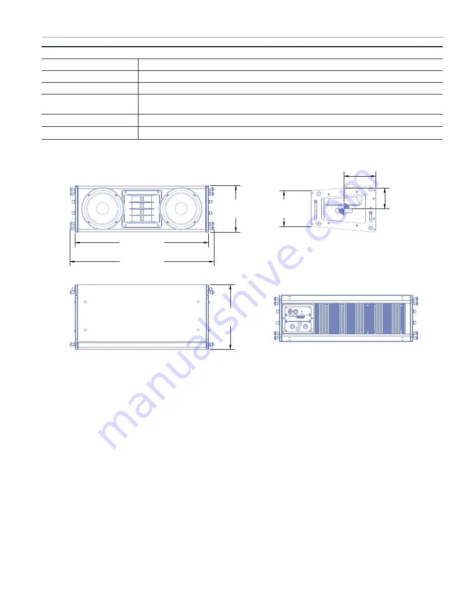
26.48

 [672.52 mm]

28.54

 [724.84 mm]

12.75

 [323.85 mm]

9.19

 [233.31 mm]

7.08

 [179.91 mm]

6.30

 [160.02 mm]

4.10
[104.14 mm]

PHYSICAL

Enclosure

Premium birch plywood

Finish

Black textured 

Protective grille

Powder-coated, hex-stamped steel, black mesh

Rigging

QuickFly rigging with four captive GuideALinks in the bottom corners of two aluminum and 

steel end frames, secured with quick-release pins

Dimensions

28.54 w x 9.19 h x 12.75 d (724.84 mm x 233.31 mm x 323.85 mm)

Weight

Weight  62 lbs (28.12 kg)

Summary of Contents for M'elodie

Page 1: ...OPERATING INSTRUCTIONS M SERIES M elodie UltraCompact High Power Curvilinear Array Loudspeaker Keep these important operating instructions Check www meyersound com for updates ...

Page 2: ...e to 6300 m 25 000ft Shock 30 g 11 msec half sine on each of 6 sides Vibration 10 Hz to 55 Hz 0 010 peak to peak excursion 2006 Meyer Sound All rights reserved M elodie UltraCompact High Power Curvilinear Array Loudspeaker Operating Instructions The contents of this manual are furnished for informational purposes only are subject to change without notice and should not be construed as a commitment...

Page 3: ...d by Meyer Sound or sold with the loudspeaker Handles are for carrying only 13 Unplug this loudspeaker during lightning storms or when unused for long periods of time 14 Refer all servicing to qualified service personnel Servicing is required when the loudspeaker has been damaged in any way such as when the power supply cord or plug has been damaged liquid has been spilled or objects have fallen in...

Page 4: ...schen Schlages auf ein Minimum zu reduzieren den Lautsprecher vom Stromnetz trennen bevor ggf ein Audio Schnittstellensign alkabel angeschlossen wird Das Netzkabel erst nach Herstellung aller Signalverbindungen wieder einstecken Der Lautsprecher an eine geerdete zweipolige Dreiphasen Netzsteckdose anschließen Die Steckdose muß mit einem geeigneten Abzweigschutz Sicherung oder Leistungsschalter ver...

Page 5: ...uency Limiter 12 Cooling System 13 CHAPTER 4 RMS Remote Monitoring System 15 Understanding the RMS module 15 Service LED Red 16 Service Button 16 Wink LED green 16 Reset Button 16 Activity LED Green 16 User Interface 16 CHAPTER 5 Line Arrays and System Integration 17 How Line Arrays Work 17 M elodie Curvilinear Array 17 High Frequencies 17 Mid to Low Frequencies 17 Designing a Line Array System 18...

Page 6: ...ue 24 Applications 24 CHAPTER 7 QuickFly Rigging 25 M elodie GuideALinks 25 Front GuideALinks 25 The MG M elodie Multipurpose Grid 26 Using the MG M elodie for Ground Stacking 27 The MTF MICA M elodie Transition Frame 27 MCF M elodie Caster Frame 28 APPENDIX A Optional Rain Hood 31 Installing the M elodie Quick Clip Rain Hood 31 APPENDIX B Optional VEAM Multipin Connector 32 APPENDIX C M elodie Sp...

Page 7: ...on Chapter 7 QuickFly Rigging shows the QuickFly rigging components available for use with M elodie including the MG M elodie top grid and MCF M elodie caster frame You ll get an overview on arraying M elodie loudspeakers in flown or ground stacked configurations Appendix A Optional Rain Hood discusses the procedure for installing the optional M elodie rain hood used in weather protected versions Ap...

Page 8: ...2 INTRODUCTION ...

Page 9: ...e to safeguard the user panel and connectors from the elements ADVANCED M ELODIE TECHNOLOGY The M elodie loudspeaker is a self powered three way design featuring drivers designed and manufactured at Meyer Sound s Berkeley California factory The low low mid section features two high power neodymium magnet 8 inch cone drivers with 1 5 inch voice coils created to meet the power requirements of the sy...

Page 10: ... This enables M elodie arrays to go from being stored in the truck to being fully rigged and back again in minutes A slot and convenient pinned knob allow each link to be quickly and easily moved and pinned for arraying or storage with no risk of fingers or hands getting caught between cabinets Figure 1 3 The MG M elodie multipurpose grid can be used both for flying and ground stacking M elodie cabi...

Page 11: ...ne Pro acoustical prediction software allows you to quickly determine the coverage frequency response impulse response and maximum output of arrayed M elodie loudspeakers as well as useful rigging information In addition to smooth integration with MICA M elodie can be supplemented with Meyer Sound subwoofers for extended low frequency bandwidth and headroom M elodie arrays can be deployed in combi...

Page 12: ...ofer M elodie is supported by Meyer Sound s MAPP Online Pro acoustical prediction program and the Galileo loudspeaker management system Once a M elodie system is designed and installed its performance can be confirmed using a SIM 3 audio analyzer system ...

Page 13: ...tral and earth ground points Figure 2 1 A sample AC power distribution block diagram LOOPING AND CABLING M elodie loudspeakers use a PowerCon 3 pole AC mains system with locking connectors to prevent accidental disconnection Two female inlets one colored blue and the other gray are provided To loop units simply attach a cable from the gray connector of the first loudspeaker system to the blue conne...

Page 14: ...r green and yellow NOTE For units shipped with VEAM all in one multipin connector please refer to Appendix B for AC Power pin out CAUTION When creating AC cables and distributions systems it is important to pre serve AC line polarity and connect earth ground on both sides of the cable M elodie loudspeakers re quire a ground connection Always use a grounded outlet and plug It is very important that...

Page 15: ... automatically turns on again after three seconds if the voltage has returned to either normal operat ing window If the M elodie loudspeaker does not turn back on after 10 seconds remove AC power immediately see previous Caution NOTE It is recommended that the supply be operated in the rated voltage windows at least a few volts away from the turn on off points This ensures that AC voltage variatio...

Page 16: ...cir cuit breakers on the loudspeaker s user panel trip the white center buttons pop out disconnect the AC power cable Do not reset the breakers with the AC connected Contact Meyer Sound for repair information CAUTION The M elodie loudspeaker re quires a ground connection Always use a grounded outlet and plug CAUTION Do not use a ground lifting adapter or cut the AC cable ground pin CAUTION Do not ...

Page 17: ... single source can drive multiple M elodie loudspeakers with a paralleled input loop creating an un buffered hard wired loop connection Network S e r v i c e W i n k R e s e t A c t i v i t y Remote Monitor System RMS3 Firmware Looping Audio Input 10k Ω Balanced Input Loop AC LOOP OUTPUT 115 230V 50 60 Hz 10A RMS 115V 12 5A RMS 230V Class 1 Wiring AC INPUT RATING 115 230V 50 60 Hz 5A RMS 115V 2 5A...

Page 18: ...ether for quick connec tion to each cabinet THE LIMITING SYSTEM Low and Mid Frequency Limiters The M elodie loudspeaker s left and right 8 inch cone driv ers are powered by separate amplifier channels each with a detector but routed to one limiter the limiter tracks both channels and uses the higher of the two values to engage By limiting both amplifier channels equally any anomalies in the frequenc...

Page 19: ...conditions and or at high continuous levels If the temperature of the heatsink reaches 75 C 167 F the On Temp LED on the rear panel turns from green On to red Temp The unit continues to operate normally even if the On Temp LED is red but this is an indication that the unit is reaching its maximum dissipation A reduction of the SPL is recommended at this point NOTE In the highly unlikely event that...

Page 20: ...14 CHAPTER 3 ...

Page 21: ...RMS communication board and in the computer RMS database until you modify it Loud speaker View labels can be modified at any time allowing you to customize how you view the data Figure 4 1 Commissioning a M elodie loudspeaker using RMS Back and forth communication between the RMS software and the M elodie makes identifying and matching loudspeak ers and icons easy Pressing the service button on the...

Page 22: ...ng state of the card will not change this is stored in flash memory When used in combination with the Service But ton the card will be decommissioned from the network and the red Service LED will blink Activity LED Green When the loudspeaker has been commissioned the Activity LED will flash continuously When the Activity LED is unlit the loudspeaker has not been installed on the network USER INTERFA...

Page 23: ...die line array system To achieve optimal results it is important to understand how these components work together High Frequencies For high frequencies M elodie uses a very precise Constant Q horn developed using Meyer Sound s anechoic chamber which provides a consistent beamwidth of coverage in the horizontal plane In the horizontal pattern of an array of M elodies these horns work to produce a w...

Page 24: ...ay elements or the angles between them TIP When more than one array is used the angle between line arrays in the horizontal plane can be changed to meet additional design requirements for example more horizontal coverage avoid wall reflections etc With two different technologies low frequency cone radiators and high frequency horn built into each M elodie cabinet achieving these goals becomes a mul...

Page 25: ... generally need a correction to compensate for energy lost over distance the correction needed is usually proportional to the distance and high frequency air absorption In the near to mid field the air absorption is not nearly as critical in this zone high frequencies need little or no additional correction TIP If your M elodie line array uses a third zone for short throws high frequencies there ma...

Page 26: ...se is critical The number of elements drastically affects the uniformity of coverage of both SPL and frequency response The number of longer throw higher SPL elements MICA and downfill M elodie needs to be carefully selected Vertical Splay Angles Changing the splay angles between cabinets has a significant impact on vertical coverage with the result that narrower vertical splay angles produce a high...

Page 27: ...und s self powered loudspeakers and interfacing directly with the SIM 3 audio analyzer the Galileo system includes digital delay lines as well as digital implementations of popular features developed over years by Meyer Sound for its acclaimed analog processors including air absorption compensation filters array correction and equalization from the CP 10 and VX 1 Figure 5 5 Galileo 616 Loudspeaker ...

Page 28: ...er operating range while low pass filters can remove unwanted mid low frequencies reproduced by the subwoofers The use of these filters reduces the area of overlap and minimizes the interaction and possible cancellations between subsystems NOTE Full range signals may be applied to Meyer Sound s self powered loudspeakers and subwoofers because they have built in active crossovers However the use of e...

Page 29: ...MAPP Online Pro button on www meyersound com After registration and upon approval an email will be sent to you with a user name and password along with the URL where you can download MAPP Online Pro Online instructions will guide you through the download and setup process When a prediction is requested data are sent over the Internet to a high powered server at Meyer Sound running a sophisticated ...

Page 30: ...M 3 audio analyzer system includes a selection of hardware options microphones and accessory cables The SIM audio analyzer system is optimized for making audio frequency measurements of an acoustical system with a resolution of up to 1 48th of an octave the high resolution enables you to apply precise electronic corrections to adjust system response using frequency and phase time domain informatio...

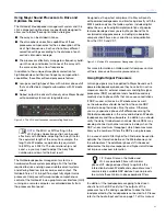
Page 31: ...liability of any rigging method for their application Rigging should be carried out only by experienced professionals CAUTION Always use properly rated rigging hardware CAUTION It is important to inspect rigging hardware regularly and replace worn or damaged components immediately M ELODIE GUIDEALINKS The M elodie loudspeaker s captive QuickFly rigging hardware features rigid GuideALinks contained...

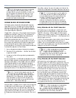
Page 32: ... angles between cabinets to fill the requirements of a venue Use the design guidelines in Chapter 5 to design systems and MAPP Online Pro to verify designs and get rigging information THE MG M ELODIE MULTIPURPOSE GRID The MG M elodie multipurpose grid allows multiple M elodie curvilinear array loudspeakers to be flown or ground stacked in numerous configurations CAUTION For complete information on lo...

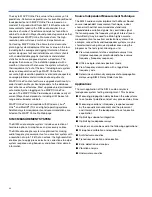
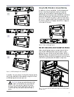
Page 33: ...ddition the up and down tilt of the MG M elodie and the array hung underneath can be adjusted using chain motors or differing lengths of steel or span set CAUTION Always use red button pins 5 16 x 0 875 or blue button pins used in M1Ds 5 16 x 1 25 to secure each grid link to the MG M elodie Avoid using the black button pins 5 16 x 0 63 since they are shorter and will not lock in place Using the MG...

Page 34: ...igure 7 11 allows you to transport stacks of up to five M elodie enclosures The M elodie GuideALinks connect the enclosures securely to the frame allowing the convenient transport of straight or splayed stacks of M elodie The steel frame surrounding the board facilitates the use of forklifts Figure 7 11 M elodie caster frame Whether you re deploying or striking an array the MCF M elodie can tempora...

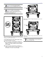
Page 35: ...e transport angles with the MCF M elodie caster frame Use the 5 position on the M elodie rear GuideALink to get the first M elodie with respect to the caster frame at 0 degrees This setting is preferred when all M elodies are at 0 degrees Use the 0 position to downtilt the first M elodie with respect to the caster frame to compensate if the rest of the M elodies in the stack have severe angles 0 3 6...

Page 36: ...TION When using the MCF M elodie caster frame to ground stack M elodie loudspeakers make sure all four caster wheels are blocked to prevent the stack from rolling away Other rigging accessories as well as a range of rugged protective transport covers are available For more information please visit www meyersound com ...

Page 37: ...he enclosure rotate the top long edge of the hood into the slot in the user panel Push the hood upward into the slot until it stops 3 Move the hood toward the enclosure until it makes contact and its side edges are within the pin receiving holes on the left and right sides of the user panel Press in to compress the foam against the enclosure 4 Holding the rain hood in place insert the black button...

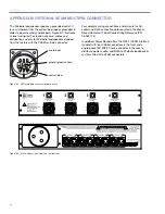
Page 38: ...llow neutral blue Figure B 1 VEAM multipin connector power pin out For complete wiring conventions and pin outs for AC audio and RMS connections please refer to the Meyer Sound document VEAM Cable Wiring Reference PN 06 033 113 In addition Meyer Sound offers the VIM 4 VEAM interface module with four VEAM connectors in the front and a single phase IEC 309 32 amp connector in the rear to distribute ...

Page 39: ...er handling is measured under AES standard conditions both transducers driven continuously for two hours with band limited noise signal having a 6 dB peak average ratio Peak power handling is measured with both transducers driven for 100 milliseconds with pink noise signal having a 12 dB peak average ratio Note To eliminate interference at shorter wavelengths the two 8 inch drivers work in combina...

Page 40: ...hat the amplifier will produce for at least 0 5 seconds into the nominal load impedance 45 V rms low channels and 47 V rms high channel Peak power based on the maximum unclipped peak voltage that the amplifier will produce for at least 100 milliseconds into the nominal load impedance 63 V peak low channels and 67 V peak high channel THD IM TIM 02 Load capacity 4 Ω low and mid 8 Ω high channels Cooli...

Page 41: ...um birch plywood Finish Black textured Protective grille Powder coated hex stamped steel black mesh Rigging QuickFly rigging with four captive GuideALinks in the bottom corners of two aluminum and steel end frames secured with quick release pins Dimensions 28 54 w x 9 19 h x 12 75 d 724 84 mm x 233 31 mm x 323 85 mm Weight Weight 62 lbs 28 12 kg ...

Page 42: ...36 APPENDIX C ...

Page 43: ......

Page 44: ... 2006 Meyer Sound Laboratories Inc 05 152 005 01 A Meyer Sound Laboratories Inc 2832 San Pablo Avenue Berkeley CA 94702 www meyersound com T 1 510 486 1166 F 1 510 486 8356 ...

Reviews: