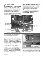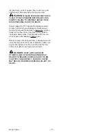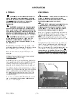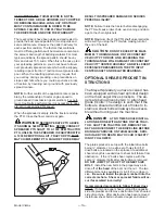
Adjust the drawbar at 13-17” above the ground. Ex-
tend or shorten the drawbar so horizontal distance
from end of tractor PTO shaft to center of hitch pin
hole is 14” for 540 RPM 1-3/8-6 spline, (16” for op-
tional 1000 RPM 1-3/8-21 spline). Secure the drawbar
so the hitch pin hole is located directly below the PTO
drive line. PTO adapters are not recommended as
damage to the drive line may occur. A hitch pin with a
minimum diameter of 1” and bottom retaining pin is
recommended.
AN IMPROPERLY LOCATED HITCH POINT MAY
CAUSE DAMAGE TO THE UNIVERSAL JOINTS OF
THE PTO DRIVE SHAFT. CONFORMING TO THE
DRAWBAR AND PTO RELATIONSHIP SHOWN ON
FIGURE 1, PAGE 8 WILL ENSURE THAT THE PTO
DRIVESHAFT WILL NOT BECOME OVER
EXTENDED. USE THE CORRECT SETTING FOR
14” - 540RPM 1 3/8-6 or 16” - 1000RPM 1 3/8-21.
WITH INITIAL HOOK-UP TO YOUR NEW MEYER
SPREADER TEST PTO TRAVEL BY TURNING
EQUIPMENT IN BOTH DIRECTIONS OBSERVING
THE MINIMUM AND MAXIMUM TRAVEL
DIMENSIONS AS SHOWN PER DRAWING ON
FIGURE 6, PAGE 15.
LUBRICATION
LUBRICATION
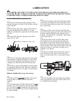
A high quality Lithium Base Grease should be used
PRIOR TO USE
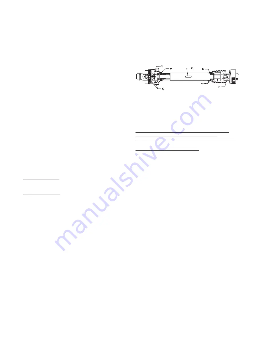
A. Using the CV Zerk (Key #2) place 20 pumps of
grease into the CV center housing. This should
be done with the drive line / CV as straight as
possible.
B. Slowly articulate the double joint through its
maximum joint angle several times.
C. Return the CV joint to its straight position and
insert additional grease into the CV Zerk (Key
#2) until grease is evident around the housing
and center sliding disk.
NORMAL OPERATION
A. Lubricate the following items after every eight
(8) hours of operation. If short rows and
frequent turning or other demanding conditions
exist, lubricate at four (4) hour intervals.
1.
Cross and bearings (Key #1)-Add grease
until it is purged around the seals.
2.
CV center housing (Key #2)-Add grease
until it is evident around the center sliding
disk.
3.
Telescoping members (Key #3)-Add
grease until it adequately covers the
sliding members. Take apart
occasionally to make sure adequate
lubrication is being added.
4.
Shield bearings (Key #4)-Add 2-3 pumps.
FAILURE TO FREQUENTLY GREASE THE CV
CENTER HOUSING AND TELESCOPING
MEMBERS WILL REDUCE THE LIFE OF THE CV.
MAINTENANCE INFORMATION
It is extremely important to follow the maintenance
guidelines. If telescoping members become hard to
slide during normal operation, it is recommended the
shaft be taken apart, cleaned with solvent and
re-coated with grease before re-assembling. As a
minimum it is important this be done after each season
of use.
Model V-Max
—16—
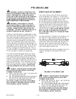
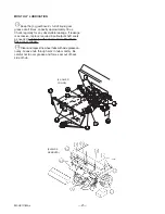
FIGURE 7. PTO DRIVE LINE
Summary of Contents for V-MAX 2636 Operators
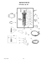
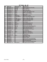
Page 24: ...Model V Max 24 REPAIR PARTS OPTIONAL OIL KIT 35 ...
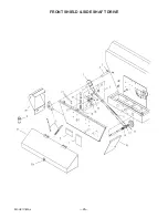
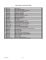
Page 26: ...Model V Max 26 FRONT SHIELD SIDE SHAFT DRIVE ...
Page 34: ...Model V Max 34 BOX AUGERS SIDE SHAFT ...
Page 36: ...Model V Max 36 UNLOADING GATE TRIP PAN DOORS Prior to 08 Serial Nos ...
Page 38: ...Model V Max 38 SPINNERS GEARBOX SHAFT DRIVE PRIOR TO 08 SERIAL NOS ...
Page 42: ...Model V Max 42 OPTIONAL THIRD AUGER Items 10 and 11 are used on two auger units only ...
Page 57: ...Model V Max 57 ...
Page 58: ...Model V Max 58 ...
Page 59: ...Model V Max 59 ...
Page 60: ...E ...

