background image

3

2

1

3

5

6

4

7

8

10   

OVERVIEW

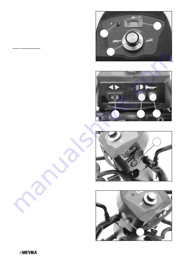
Operating module

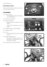
The overview shows the operating controls 
of the operating module.

Pos. Description

(1)  Status indicator


– Control gauge for operational readi-

ness / error display.

(2)  Battery voltage gauge
(3)  Speed preselection


– Rabbit (highest selectable max. final 

speed)


– Turtle (lowest selectable max. final 

speed)

(4)  Toggle switch turn signal left/right
(5)  Lighting ON/OFF
(6)  Horn


– When pressing this key a horn signal 

sounds.

(7)  Battery charging socket


– The battery charging socket is pro-

tected by a cover plate that can be 
swivelled to the side.

(8)  Hazard warning indicator ON/OFF

Summary of Contents for 1.254

Page 1: ...en Operating manual W e m o v e p e o p l e Scooter Model 1 254...

Page 2: ...iation 8 Overview 9 Model 1 254 9 Operating module 10 Tips for accident prevention 11 First driving practice 11 Safety information 11 Handling of the Scooter 12 Securing the Scooter 12 Functional chec...

Page 3: ...18 Preselecting the final speed 18 Actuator 19 Forward driving speed 19 Backwards driving speed 19 Left right turns 19 Braking down the Scooter 19 Selecting the operation 20 Pre operation checks 21 B...

Page 4: ...0 Batteries 30 Stillstand for more than four months 30 Retaining strap 31 Fastening the retaining strap 31 Opening the retaining strap 31 Adjustment of belt length 31 Maintenance 32 Maintenance 32 Mai...

Page 5: ...7176 15 for model 1 254 42 Further technical data for model 1 254 43 Meaning of the labels on the Scooter 45 Meaning of the symbols on the type plate 46 Inspection certificate 47 Warranty Guarantee 48...

Page 6: ...the Informa tion center on our website www meyra com Our implemented assembly groups and components fulfil the demands of the norms of correspondence acc to EN 1021 2 for durability against inflaming...

Page 7: ...or extreme cold You must not let yourself be carried in your wheelchair through the lifting of the wheel chair Parts that are not securely fixed e g seat revetment parts can become loose and thus cau...

Page 8: ...ents of the EG di rective 93 42 EWG for medical devices Nev ertheless Interferences from high frequency rays of other electric devices cannot gener ally be ruled out Despite tested protective measures...

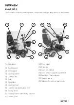
Page 9: ...ive key 14 Lever for seat lock 15 Lever for back support adjustment 16 Back light Rear indicator 17 Support castor 18 Selection lever drive push mode Pos Description 1 Head support 2 Arm support 3 Ste...

Page 10: ...isplay 2 Battery voltage gauge 3 Speed preselection Rabbit highest selectable max final speed Turtle lowest selectable max final speed 4 Toggle switch turn signal left right 5 Lighting ON OFF 6 Horn W...

Page 11: ...anger of tilting when driving backwards on ramps The support castors can touch the ground while driving down e g in front of the edge of an obstacle which can cause the drive wheels to lift off the gr...

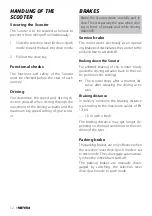
Page 12: ...Service brake The motor works electrically as an operat ing brake and decelerates the scooter softly and jerk free to a standstill Braking down the Scooter For allotted braking of the scooter slowly...

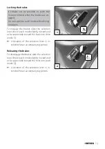
Page 13: ...ever drive push mode slightly inward and as far as possible toward the back into drive mode 1 Activation of the selection lever is in tended for an accompanying person Releasing the brakes To disengag...

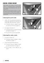
Page 14: ...the operating module be cause the pushing will otherwise be made difficult by the electric system Therefore observe chapter Operat ing module functions on page 16 2 Disengage the brakes 1 Therefore o...

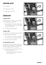
Page 15: ...2 The Scooter is switched off Position ON The driving key is inserted as far as possible into the driving key socket 2 For switching on turn the driving key from position 2 clockwise by 90 3 The driv...

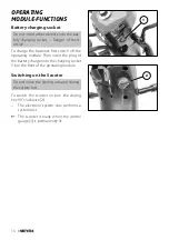
Page 16: ...the operating module Then insert the plug of the battery charger into the charging socket 1 on the front of the operating module Switching on the Scooter Do not move the driving actuator during the sy...

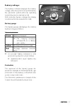
Page 17: ...follows The colours mean Green Batteries charged The charging condition corresponds to a display of 0 100 Yellow Recharging recommended Red Recharge batteries immedi ately An accurate battery indicat...

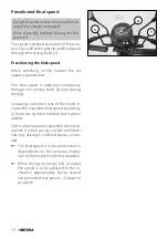
Page 18: ...inuously through the turning knob 2 also during driving Increasing clockwise turns of the knob in crease the maximum final speed according ly from slow symbol turtle to fast symbol rabbit Select a low...

Page 19: ...y in the direction of he arrow until you reach the desired driving speed Backwards driving speed Move the left side of the driving actuator lever 2 slowly in the direction of the arrow The final speed...

Page 20: ...he brakes Observe chapter Locking the brakes on page 13 3 Check the position of he steering col umn In order to position the steering col umn press the adjustment lever 3 up ward The steering column i...

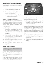
Page 21: ...er Fault correc tion on page 36 View chapter Battery voltage on page 17 Recharging batteries Solely use a charger that corresponds to the type of battery The batteries should be charged right after th...

Page 22: ...e charger plug into the battery charging socket 1 of the operating module 3 Switch the battery charger on resp insert the main plug of the battery charger into the corresponding power socket The batte...

Page 23: ...sfer to or from the seat 2 After activating the release lever 4 the seat can be turned After each 45 step the seat locking de vice engages automatically Removing the seat Grab sideways under the seat...

Page 24: ...g lever lock into place Check the locking device of the seat Adjustment of the seat height Have the adjustment of the seat height con ducted by an authorised specialist work shop Adjusting the distanc...

Page 25: ...back ward in several steps 1 or lowered forward onto the seat surface 2 For adjusting the back support press the lever of the back support adjust ment 3 down After the adjustment let the back sup port...

Page 26: ...is continuously adjustable by adjusting the stopper screw 2 Remove the arm support To remove the arm support 3 screw back the locking screw 4 rather far When the locking device is released the arm sup...

Page 27: ...ard up to the marker After the height adjustment retighten the clamping screw 1 Adjusting the headrest height After activating the locking spring 2 the height of the head support can be adjusted After...

Page 28: ...this observe chapter Securing the Scooter on page 12 2 Remove the seat 1 Therefore observe chapter Seat on page 23 3 Remove the front basket 4 Folding down the steering column 2 Press the adjustment l...

Page 29: ...SEATBASKET OPTION With increasing weight inside the basket the risk of tilting backwards increases Do not place valuable items such as wal lets openly inside the basket Unwanted loss of valuable items...

Page 30: ...astors do not provide suffi cient protection against tipping over in certain situations BATTERIES Stillstand for more than four months In case of a stillstand of the Scooter of more than four months c...

Page 31: ...ects are trapped between belt and the body Thus you avoid painful pressure points Pull both belt halves to the front and slide the catch halves together so that they latch together 1 Afterwards conduc...

Page 32: ...maintenance results in a limitation of the product liability Maintenance The following maintenance Instruction gives you a guide for carrying out the main tenance work They do not give information ab...

Page 33: ...ened ad justment screws Contact specialist workshop upon demand Every 2 months depending on dis tance covered Check the wheels Carry out a visual check your self or with a helper If the tyre profile i...

Page 34: ...34 WHEN WHAT REMARK Manufacturer recom mendation Every 12 months depending on fre quency of use Maintenance jobs Vehicle Battery charger To be carried out by the spe cialist dealer...

Page 35: ...cooter on a level surface and secure it from rolling away Therefore observe chapter Securing the Scooter on page 12 New fuses can be obtained for example at petrol stations If the safety fuse blows ag...

Page 36: ...r supply without contact Check the plug connec tions Batteries deep discharged Have it repaired by the specialist workshop The battery gauge blinks after the switch on The selection lever drive push m...

Page 37: ...soft soap When using commercial plastic cleansers the manufacturers application instructions are to be observed Finish The high quality finish ensures an optimum of protection against corrosion Shoul...

Page 38: ...r local specialist dealer who will provide counselling customer ser vice and repairs Spare parts Safety relevant parts or assembly groups are only to be assembled in a specialist workshop Danger of ac...

Page 39: ...39 Disposal The disposal must comply with the respec tive national law Please enquire about local disposal arrange ments at your municipal authority...

Page 40: ...ould be recorded in the operating manual A draft for further inspection certificates can be copied from the maintenance and ser vice manual when required It then has to be added to the operating manua...

Page 41: ...ominal load of 100 kg Without repeated acceleration Level firm driving surface The maximum range is greatly reduced by frequent driving upwards on ramps insufficient charging condition of the drive ba...

Page 42: ...mm 660 mm Seat angle 4 8 4 8 Back support angle 45 45 Back support height 450 mm 450 mm Footplate to seat lower shank length 520 mm 520 mm Static stability downhill 9 9 Static stability uphill 9 9 Sta...

Page 43: ...mitted axle load front 79 kg 79 kg Permitted axle load rear 159 kg 159 kg Ground clearance 100 mm Empty weight with battery pack kg 91 5 kg Empty weight without battery pack kg 70 0 kg Overall height...

Page 44: ...pneumatic tyres max 3 5 bar Driving wheel 3 00 4 10 pneumatic tyres max 3 5 bar Drive batteries 2 x 12 V 28 1 Ah 5 h 35 Ah 20 h maintenance free Max battery dimensions LxWxH 195 x 130 x 170 mm Chargin...

Page 45: ...ating manuals and other provided documen tation Do not lift the Scooter at the arm supports or leg supports Removable parts are not suitable for carrying Drive mode Push mode Push only on level surfac...

Page 46: ...x permissible total weight Permitted axle weights Max permissible rising gradient Max permissible falling gradient Permitted maximum speed The product is approved as a seat within a motor vehicle Max...

Page 47: ...st dealer Next safety inspection in 12 months Date Place date Signature Stamp of specialist dealer Next safety inspection in 12 months Date Place date Signature 47 Recommended safety inspection 1st ye...

Page 48: ...nuts as well as worn out attachment holes due to frequent assembly work Furthermore damage to the drive and elec tronics caused by improper cleaning using steam cleaning equipment or the deliberate o...

Page 49: ...e specialist dealer Serial no SN Delivery note no Model Stamp of specialist dealer Next safety inspection in 12 months Date Place date Signature 49 Warrantee Guarantee section Please fill out Copy if...

Page 50: ...50 NOTES...

Page 51: ...51 NOTES...

Page 52: ...a Ring 2 D 32689 Kalletal Kalldorf Tel 49 5733 922 311 Fax 49 5733 922 9311 info meyra de www meyra de Your specialist dealer 205 346 001 Status 2018 06 All technical modifications reserved Original o...

Reviews: