38
31
ADJUSTING THE ANGLE OF
THE BACK SUPPORT
Mechanical back support ad-
justment
Switch off the wheelchair. Move
the brake release lever into the
drive position. This prevents
the wheelchair from rolling away
accidentally.
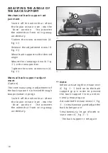
Slacken the screw connection (A,
fig. 31).
Remove the adjustment screw (B,
fig. 31).
Move back support to the desired
angle.
Mount the clamping screw (B, fig.
31) in the new position.
Tighten the screw connection (A,
fig. 31).
Manual back support adjust-
ment
(Option)
The continuous angle adjustment of
the back support is achieved through
two pneumatic springs.
Switch off the wheelchair. Move
the brake release lever into the
drive position. This prevents
the wheelchair from rolling away
accidentally.
+
Note:
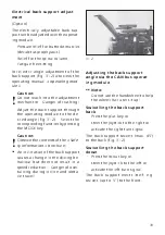
Before activating the release lever
(C, fig. 31.1) hold on to the back
support grip in order to prevent
the back support from uninten-
tionally snapping up.
Activate both release levers (C, fig.
31.1) simultaneously and adjust the
back tubes parallel.
Simultaneously let go of both re-
lease levers (C, fig. 31.1).
The back support is set again.
31.1
A
C
B

