33
DRIVE
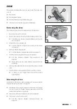
The vehicle is fitted with a drive on each side. The drive con-
sists of:
(1) the motor,
(2) the magnetic brake,
(3) the maintenance free differential gear.
☞
The drive can only be replaced completely.
Removing the drive
The following describes the replacement of the drive.
1. Securely jack-up the vehicle.
2. Switch the vehicle off and pull the battery-/mains fuse.
☞
Therefore also observe chapter
Working on the vehi-
cle
on page 6.
3. Detach the drive wheels [4].
☞
For this observe chapter
Disassembly of the wheels
on page 23.
4. Remove the front panel [5].
☞
For this observe chapter
Revetment
on page 25.
5. Pull the motor plug from the power module.
☞
For this observe chapter
Plug assignment
on
page 42.
☞
Open all necessary cable binders required for dis-
assembly.
6. Remove the attachment screws (6) of the drive on both
sides.
7. Pull the drive out toward the front out of the rockers.
☞
In doing so you might need to pull the rockers
apart slightly.
Mounting the drive
Assembly of the drive is done analogue in reverse order to
chapter
Removing the drive
on page 33.
☞
Retighten all loosened screwed connection The torque
can be found in chapter
Torque according to DIN for
screwed connections
on page 49 .
☞
Previously removed cable ties are to be replaced.
☞
Then carry out a function test.
☞
For this observe chapter
Functional checks
on
page 46.
1
2
3
4
5
6
Summary of Contents for 2.322
Page 8: ...8 OVERVIEW Model 2 322 R Net operating module ...
Page 51: ...51 NOTES ...


