background image

15

14

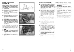
Batteries should only be charged with
a battery charger that is suitable for
the type and rating of the batteries.
The guarantee is only preserved to its
full extent when the supplied and rec-
ommended battery charger is used.
Your authorised dealer will be pleased
to help you choose the correct battery
charger.

Charge the batteries:

– before long tours,

– after a long journey,

– whenever the use permits.

!

Attention:

Observe the brochure < 

Safety in-

formation electronic vehicles

 >!

Avoid sparking by static electricity
(e.g. caused by synthetic flooring
or use of the vehicle during the
charging process).

Observe the contents of the oper-
ating manual for the battery charg-
er.

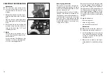
Recharging batteries

The batteries should be charged im-
mediately after the daily use in order
to have the full driving distance avail-
able on the next day.

Every battery has a normal “self-dis-
charge”. The batteries should be re-
charged once a month when the elec-
tric wheelchair is not used for a long
period of time. The batteries should
be recharged once a month when the
electric wheelchair is not used for a
long period of time.

SELECTING THE OPERATION

!

Attention:

The functions and safety of the
electric wheelchair must be
checked before the start of each
journey.

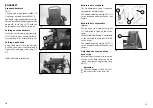
1. Charge the batteries via the oper-

ating module before the first jour-
ney.

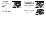
– Fig. 6 shows the operating module

with plugged-in battery charger
plug.

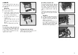
2. Move the drive motors to the drive

mode position. Push the selection
lever to the front (fig. 7/ 

) until

it audibly latches.

Note:

The key function enables you to
secure the wheelchair against un-
authorised use.

For this observe the chapter < 

key

function 

> in the operating manu-

al of the operating module.

7

6

1

Summary of Contents for RUNNER 1.445

Page 1: ...1 ELECTRONIC WHEELCHAIR RUNNER Model 1 445 OPERATING MANUAL The Motivation GB...

Page 2: ...Horizontal adjustment 19 Vertical adjustment 19 Remove the operating module 20 Fitting of the operating module 20 Turning the operating module to the side 20 Loading and transportation 21 Safety infor...

Page 3: ...ep climber 47 Crossing an obstacle 47 Remove the step climber 48 Mounting the step climber 48 Lighting 49 Service 50 Care 50 Repairs 51 Customer Service 51 Spare parts 52 Batteries 52 Unsealed batteri...

Page 4: ...d to pre vent accidents Children should read this operating manual the operating manual Op erating module and the Safety information dor electric vehicles bro chure together with the parents or a supe...

Page 5: ...irst driving exercises A low maximum speed must be pre selected on the control unit for the initial driving practice Make yourself familiar with the driving behaviour of the electric wheelchair in sma...

Page 6: ...ns Note The technology of this electric wheelchair complies with the re quirements of the EEC 93 42 direc tive on electromagnetic compati bility However the possibility of interference from high frequ...

Page 7: ...itching the operating module on The vehicle is now ready for driving again 5 4 DRIVE PUSH MODE The lever fig 3 for switching the drive motors between the drive mode and push mode is located on the rig...

Page 8: ...e daily use in order to have the full driving distance avail able on the next day Every battery has a normal self dis charge The batteries should be re charged once a month when the elec tric wheelcha...

Page 9: ...f the wheel chair An unintentional operation of the joystick will otherwise cause the wheelchair to travel Danger of accidents For safety reasons never operate a mobile phone or other transmit ting de...

Page 10: ...Have the brakes repaired immedi ately by an authorised dealer if they work one sided or if the brak ing effect is reduced Observe the brochure Safety in formation electronic vehicles Service brake Th...

Page 11: ...s 15 Remove the operating module To remove the control unit slacken the clamping screw fig 13 Pull the operating module to the front Note Carefully route the cable when doing this Fitting of the opera...

Page 12: ...To secure the wheelchair use the front crossbrace fig 16 as well as the loops at the side fig 17 Do not use the armrests legrests or the push bar for lashing the wheel chair Only use permitted fasten...

Page 13: ...the ground end or at the trans port vehicle end Ramps should be positioned so as to leave enough space for wheel chair steering correction without one of the wheels protruding over the edge of the ram...

Page 14: ...EAT Folding over the seat strap For cleaning and maintenance work on the batteries the seatbelt can be folded over to one side fig 21 1 Pull the back flap off of the seat strap Velcro fastener 2 Lift...

Page 15: ...lination The seat inclination can be adjusted into an angle of 4 to 12 in six steps fig 27 Attention Adjust the seat angle only when the wheelchair is standing on a level surface A danger of tipping o...

Page 16: ...can be ad justed through the single straps fig 34 Attention The overlapping of the Velcro fas tener has to be at least 10 cm 33 ORTOFLEX Upholstery ORTOFLEX Strap part Standard Seat cover Standard Bac...

Page 17: ...m sliding down WW Wrench width mm 38 1 39 Height adjustment with height stopper Option Slacken the clamping screw fig 31 and slide the end stop fully up and lightly tighten the clamping screw fig 39 P...

Page 18: ...1 44 42 Remove the armrest Fig 40 Slacken the clamping screw fig 41 and pull off the armrest upwards Note The operating module must be re moved first if the armrest on the control side is to be detac...

Page 19: ...swivelled in the legrests again 48 47 49 1 1 LEGRESTS Various legrest models for the wheel chair are available The foot plates can be folded up Attention Do not use the legrests to lift or carry the w...

Page 20: ...clamping screw Attention The marking hole shows the max imum extension 53 1 54 2 55 1 Remove the legrests Undo the calf strap at one side before removing the legrests Pull up the locking device fig 50...

Page 21: ...Adjusting the height of the legrests You raise the legrest by simply pull ing it up to the desired height To low er the legrest hold the legrest and then press down the lever fig 56 Positioning the c...

Page 22: ...sure that no objects are trapped between belt and the body Thus you avoid painful pressure points 60 2 1 3 OPTIONS Options are not a part of the standard scope of supply Note Options from other compan...

Page 23: ...tment Hold the operating module and then slacken the clamping screw fig 64 Swivel the operating module into the desired position and retighten the clamping screw 64 1 HEADREST The headrest fig 61 is s...

Page 24: ...ed back rest Driving on a rising falling gradi ent especially without a lap belt Oblique crossing of an obstacle Additional luggage behind the backrest or hung one sided on an armrest Driving with too...

Page 25: ...13 Remove the clamping screw fig 69 First pull the step climber forward then remove it to the top Mounting the step climber Hook in the step climber over the front frame tube and align it to lie centr...

Page 26: ...An authorised dealer has been trained by us in our factory according to our guidelines and can give advice and carry out maintenance servicing and repairs We have a large network of dealers in germany...

Page 27: ...an authorised workshop because they know about the pos sible risk situations and can correct ly dispose of defective batteries Safety informations Keep children away from batteries accessory parts an...

Page 28: ...ecking or topping up un sealed batteries Use only distilled water for topping up unsealed batteries Use a metal funnel for filling or topping up Danger of short cir cuit Maintenance the batteries Remo...

Page 29: ...acid level in the tube is lower than the scale value of 1 18 kg dm The battery is fully charged if the acid lev el is above the scale value of 1 28 kg dm The acid density difference between the indiv...

Page 30: ...ide pin then press in the lens and fasten it with the securing screw fig 82 81 82 LIGHTING Option Headlamps Filament bulb 12V 3W E10 Tools Phillips screwdriver Note Use a dry cloth to hold the glass b...

Page 31: ...in the lens and fasten it with the securing screws fig 86 85 86 Rear indicator Spherical bulb 24V 21W BA15s Tools Phillips screwdriver Note Use a dry cloth to hold the glass body of the new filament b...

Page 32: ...wheel change is not permitted The wheelchair must stand on a level and firm surface Be fore starting the disassembly work support the frame to prevent the wheelchair from tipping over and se cure it t...

Page 33: ...at annual intervals Annual service intervals are required under normal operating conditions Shorter intervals for brakes and chas sis checks are recommended in the case of severe operating conditions...

Page 34: ...ut that the system re lated hill climbing ability is much higher because this ability must be made available for the safe crossing of obstacles User weight of 75 kg Normal road surface Rising falling...

Page 35: ...ngth seat cover without cushion 33 to 46 cm Thigh length ERGOpor 39 to 52 cm Drive wheel pneumatic tyres 2 5 bar max 12 x 2 330 x 62 mm Swivel wheel pneumatic tyres 2 5 bar max 8 x 2 200 x 50 mm Trans...

Page 36: ...see Kilometric performance Max forward top speed approx 6 km h Obstacle crossing upwards approx 50 mm Obstacle crossing upwards with step climber approx 110 mm Obstacle crossing downwards approx 50 m...

Page 37: ...orised dealer Next safety inspection in 12 months Date Place date Signature Recommended safety inspection at least every 12 months Stamp of authorised dealer Next safety inspection in 12 months Date P...

Page 38: ...tion number Fz I Nr and your retailer The vehicle identification number Fz I Nr is indicated on the type plate This guarantee is offered subject to the use of the wheelchair as per instruc tions and t...

Page 39: ...the authorized dealer MEYRA Wilhelm Meyer GmbH Co KG Company address Meyra Ring 2 D 32689 Kalletal Kalldorf Telephone 49 0 5733 922 311 Telefax 49 0 5733 922 143 e mail info meyra de Internet http ww...

Reviews: