background image

25

BATTERIES
Charging the batteries

Charging lead-acid batteries:
– before long tours
– after long periods of disuse
– when the red warning light of the

battery symbol (LED display) is on or
blinks.

– when the battery symbol for approx.

10% battery capacity appears on
the LCD display.

It is best to charge the battery overnight.
Full recharging of the batteries takes 12
to 15 hours.

Charging Gel batteries:
The 100% charging of maintenance-
free batteries is only possible for physi-
cal reasons over an extremely long
charging period (>36 hours). If the bat-
tery display indicates that the battery is
fully charged, this corresponds to 90-
95% of nominal capacity.

+

Remark:

Recharge the batteries as often as
possible.

Charging before long periods
of non-use

You should fully charge the batteries of
the wheelchair before a long  period of
non-use. – This lengthens the service life
of the batteries. Pull out the main fuse
after the charging and re-insert it into the
fuse holder the other way round. This
prevents the fuse being lost.

Battery charger
 

Only use a battery charger which is

designed for the battery in question! –
Otherwise, the batteries may be de-
stroyed.
Observe the operating manual.

Charging procedure

Do not recharge the batteries in a damp
room or enclosed space. – The charg-
ing process can produce toxic fumes.
Ensure that the room is well-ventilated!

– Switch off the wheelchair and move

the brake release lever to the "drive"
position. – This prevents the wheel-
chair from rolling away accidentally.

– Insert the plug of the battery charger

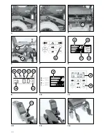
into the battery charging socket (A,
Fig. 39) of the control box (Fig. 41).

– Insert the mains plug of the battery

charger into an appropriate mains
socket.

The battery is now charging.

!

Attention:

Do not insert any objects other than
the supplied charging plug into the
battery charger. – Danger of short
circuit!

• Do not insert charging plugs on other

wheelchairs into the battery socket!

+

Remark:

The charging process only runs
when the main fuse (A, Fig. 5) is not
defective.

Battery maintenance

Always remove the main fuse (Fig. 40)
before working on the batteries or elec-
trical/electronic components.

!

Attention:

Do not touch the battery terminals
with tools, cable ends or other metal-
lic items. – Risk of short circuit and
explosion!

• Avoid naked flames and sparks in the

vicinity of the batteries. – Risk of ex-
plosion!

• Observe the contents of the 'General

information on electrical systems' and
'Maintenance' sections of the 'Safety
information' brochure.

+

Remark:

Water can collect in the battery
box when driving in rain in unfa-
vourable conditions. Collected
water should only be removed by
a specialist workshop. – Risk of inju-
ry from acid!

Maintenance-free batteries

Vent plugs are not visible. – No mainte-
nance is required. Acid-tightness cannot
be measured.

Summary of Contents for SPRINT GT 2.593

Page 1: ...1 ELECTRONIC WHEELCHAIR D GB F I E NL SPRINT GT Model 2 593 OPERATING MANUAL WHEELCHAIRS AND REHABILITATION EQUIPMENT...

Page 2: ...of control box 11 Keyboard 12 Adjustment options 13 Securing with the LCD combination lock 16 LCD backlighting 17 Control for accompanying person code 851 17 Swivelling control box code 836 17 Legrest...

Page 3: ...heel chair both indoors e g at home at your place of work and outdoors This operating manual will give you all the information you require clearly written and with illustrations Attention Before you m...

Page 4: ...is the standard version All deviations are specified separately in this operating manual Fig 1 and 1a show the model 2 593 No Designation 1 Push handle 2 Backrest upholstery 3 Side part with armrest 4...

Page 5: ...e wheelchair when traveling downhill at high speed can cause it to skid Danger of acci dents When traveling downhill select a low speed Avoid jerky adjustments to driving status when negotiating hills...

Page 6: ...e push mode At the same time they guarantee the automatic brak ing of the wheelchair in the event of a power failure You switch the safety magnetic brakes from the drive mode to the push mode with the...

Page 7: ...he zero position centre posi tion for more than 2 seconds after the drive key has been removed 5 Switch on control box Press the ON OFF key 34 on the key field of the control panel Fig 7 The LED of th...

Page 8: ...he battery and the type of load It should therefore only be taken as an approximate value If doubt exists the daily kilometre indi cation should also be considered for a better estimation of the remai...

Page 9: ...gh Accident risk due to oncoming vehicles Top speed indication on LED control box Fig 10 The top speed has a default setting of 100 after the control box has been switched on by pressing the ON OFF ke...

Page 10: ...n Level 4 100 maximum top speed Level 3 75 almost max top speed Level 2 50 top speed reduced to one half Level 1 25 greatly re duced top speed CONTROL BOX THE LCD DISPLAY liquid crystal display 39 War...

Page 11: ...sition marking indicates max point Removal Slacken the adjusting screw A Fig 6 and pull the control box 13 forwards out of the guide Attention Operation of the wheelchair after removing the control bo...

Page 12: ...sher on or off Left direction indicator key 26 Switches the left indicator on or off Right direction indicator 32 Switches the right indicator on or off Minus key 24 Each key press reduces the top spe...

Page 13: ...rol box has been switched on You can call up the next function on the function display by pressing the MODE key 42 The number of available func tions depends on the optional equipment fitted to the wh...

Page 14: ...n CONTROL BOX ADJUSTMENT OPTIONS 3 Backrest adjustment code 25 code 567 Joystick to the right backrest swivels to the rear 45 max Joystick to the left backrest swivels to the upright position 4 Seat t...

Page 15: ...e key pressing decreases the switch off time Joystick to the right switch off time increases Joystick to the left switch off time decreases 0 Speed Shows the momentary driving speed Example A switch o...

Page 16: ...rd correct digit has been en tered Three zeroes will appear on the LCD display Deactivation of combination lock The wheelchair is ready to drive and secured The LCD display shows the speed indication...

Page 17: ...ositioned for the ac companying person by way of adjusting screws Remark A special side part armrest for mounting the control box is re quired for the relocation of the con trol box from the push bar...

Page 18: ...er into and out of the wheelchair Leg region free no stumbling Handling Switch off the wheelchair and move the brake release lever to the drive position This prevents the wheel chair from rolling away...

Page 19: ...se lever to the drive position This prevents the wheel chair from rolling away accidentally Whilst sitting in the wheelchair raise or lower the legrest Fig 22 to the desired height via the control box...

Page 20: ...release lever to the drive position This prevents the wheel chair from rolling away accidentally Remove the legrests if necessary Pull the locking knob A Fig 26 and swivel down the seat unit Fig 27 At...

Page 21: ...e brake release lever to the drive position This prevents the wheel chair from rolling away accidentally Push the armrest outwards inwards This is carried out by loosening the relevant adjusting screw...

Page 22: ...lifting equipment which is approved by MEYRA SAFETY BELT Code 833 The purpose of the safety belt is to strap in the wheelchair user Benefits Additional stabilization of the sitting position Prevents u...

Page 23: ...must only be secured to the front and rear securing eyes Fig 37 of the wheelchair and securing points intended for such purpose in the car Remark Suitable fixing points can usually be found in the ca...

Page 24: ...structions for the wheelchair This ensures that no incorrect details will be given for future orders of spare parts Remark Maintenance modification work and adjustments on the wheelchair should only b...

Page 25: ...s can produce toxic fumes Ensure that the room is well ventilated Switch off the wheelchair and move the brake release lever to the drive position This prevents the wheel chair from rolling away accid...

Page 26: ...Open the Velcro fastener of the strap Fig 42 6 Lift off the battery cover Fig 43 7 Wipe the surface of the battery with a dry cloth 8 Dismantle the battery terminal clips 9 Raise the carrying handle...

Page 27: ...ding on distance covered Before starting out Test brakes for faultless operation Move the brake release lever 11 to drive mode It should now be impossi ble to push the wheelchair If this is not the ca...

Page 28: ...ig 52 Press the faulty bulb against a holding frame and remove Mounting Insert a new bulb Place one tip into one hole on the fixture then the other tip into the other hole Fig 52 Mount the lens First...

Page 29: ...ent is located in the fuse holder under the seat A Fig 5 Pulling out the main fuse during driving causes an immediate stopping of the wheelchair Danger of accidents SPRINT GT model 2 593 Main fuse for...

Page 30: ...ing bar flashes on the LCD display if there is a malfunction The error codes help the specialist work shop to quickly identify the cause of the malfunction The electronics performs a self test after t...

Page 31: ...mpaired by frequent uphill travel low battery charging status low ambient temperature e g in winter frequent acceleration and braking e g in city traffic old sulphated batteries unavoidable frequent s...

Page 32: ...D 0 5 9 3 m c t h g i e h t s e r k c a B 5 4 m c s t s e r m r a f o t h g i e H 5 2 0 2 e s u r o f y d a e r t r o p s n a r t m c h t g n e L 3 1 1 5 8 m c t h g i e H 2 0 1 6 5 m c h t d i W 7 6...

Page 33: ...tailer stamp Next safety inspection in 12 months Date Place date Signature Recommended safety inspection at least every 12 months Retailer stamp Next safety inspection in 12 months Date Place date Sig...

Page 34: ...pection in 12 months Date Place date Signature Recommended safety inspection at least every 12 months Retailer stamp Next safety inspection in 12 months Date Place date Signature Recommended safety in...

Page 35: ...e identification number Fz I Nr is on the type plate on one side of the crossbrace Failure to observe instructions in the op erating manual incorrectly carried out maintenance work and especially tech...

Page 36: ...Retailer stamp MEYRA Wilhelm Meyer GmbH Co KG Company address Meyra Ring 2 D 32689 Kalletal Kalldorf Telephone 49 0 5733 922 0 Telefax 49 0 5733 922 143 e mail info meyra de Internet http www meyra de...

Page 37: ...stration Section of the Operating Manual Illustration du mode d emploi Illustrazioni relative alle istruzioni d uso Fotos para las instrucciones de funcionamiento Afbeelding voor Gebruiksaanwijzing EL...

Page 38: ...38 SPRINTGT MODELL2 593 1 3 2 1 4 5 6 7 8 9 1a 10 11 12 13 16 15 14...

Page 39: ...39 2 Abb 2a 2b 30 39 29 37 23 36 40 37 38 32 33 31 35 34 26 25 27 23 24 29 28 37 30 41 27 42 MODE...

Page 40: ...40 A 3 4 6 7 9 12 13 5 8 11 14 10 34 37 27 B 30 30 4 100 3 75 2 50 1 25 27 MODE 41 35 29 27 36 37 40 27 38 34 A...

Page 41: ...41 A 15 16 18 19 21 22 24 25 17 20 23 26 R L A A...

Page 42: ...42 A 28 30 32 33 37 31 34 27 29 35 36 B A C h...

Page 43: ...43 44 46 39 41 42 40 43 38 45 47 48 49 A A...

Page 44: ...vorbehalten Stempel vom Fachh ndler MEYRA Wilhelm Meyer GmbH Co KG Firmensitz Meyra Ring 2 D 32689 Kalletal Kalldorf Telefon 05733 922 0 Telefax 05733 922143 Email info meyra de Internet http www meyr...

Reviews: