28
SERVICE
LIGHTING
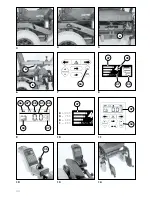
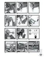
Switch off the wheelchair and pull out
the main fuse (A, Fig. 5) before replac-
ing a defective bulb (Fig. 40).
Headlight setting
The headlights should be set in such a
way that the light cone is visible on the
road. – The lower edge of the light
cone should be set at distance of 3 me-
ters to the front of the wheelchair.
Tools: screwdriver
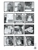
– Loosen the fastening screws (A, Fig
47) and
– set headlights.
– tighten fastening screws.
Replacing a headlight bulb
Filament bulb:
24V/3W E10
Tools: Phillips screw driver
Removal:
– Loosen the fastening screw and re-
move the lens cover (Fig. 48).
– pull the socket with bulb out of the
lens.
– Unscrew the faulty bulb from the
socket, (Fig. 49).
Mounting:
– Screw the new bulb in the socket,
(Fig. 49). – The earth wire is posi-
tioned above the thread of the sock-
et.
– Place the socket with bulb in the lens.
– Mount the lens, (Fig. 47). – First in-
sert the top pins, then press the lens
downwards and screw into place.
Back light
Filament bulb:
Festoon bulb 24 V/C5W S8.5
Tools: Phillips screw driver
Removal:
– Loosen the fastening screws and re-
move the lens cover (Fig. 52).
– Press the faulty bulb against a holding
frame and remove.
Mounting:
– Insert a new bulb. – Place one tip
into one hole on the fixture, then the
other tip into the other hole (Fig. 52).
– Mount the lens. – First insert the top
pins (Fig. 53), then press the lens
downwards and screw into place.
Front indicator
Ball lamp:
24V/10W BA15s
Tools: Phillips screw driver
Removal:
– Loosen the fastening screw and re-
move the lens cover (Fig. 50).
– Press the faulty ball lamp slightly in-
wards, turn and remove from the
socket.
Mounting:
– Insert a new ball lamp. – Push the
side pins (bayonet catch) into the
frame, exert slight pressure against
the spring and turn until the bayonet
catch clicks into place (Fig. 50).
– Mount the lens. – First insert the top
pins (Fig. 51), then press the lens
downwards and screw into place.
Rear indicator
Ball lamp:
24V/21W BA15s
Tools: Phillips screw driver
Removal:
– Loosen the fastening screws and re-
move the lens cover (Fig. 52).
– Press the faulty ball lamp slightly in-
wards, turn and remove from the
socket.
Mounting:
– Insert a new ball lamp. – Push the
side pins (bayonet catch) into the
frame, exert slight pressure against
the spring and turn until the bayonet
catch clicks into place (Fig. 52).
– Mount the lens. – First insert the top
pins (Fig. 53), then press the lens
downwards and screw into place.


