29
Fault
Cause
Clearance
LED / LCD display does not light up
after the wheelchair has been
switched on.
Wheelchair does not move forward.
Lighting not active.
Warning light [26] blinks when the
hazard warning indication is not
switched on.
Main fuse defective.
The brake release lever is set to push
mode.
Bulb defective.
Lighting or electronics fuse defective.
Malfunction in the electronics.
The main fuse for the battery circuit is
defective (blade-type fuse) or not insert-
ed deep enough.
Replace fuse.
Move the brake release lever to drive
mode.
Fit new bulb.
Replace defective fuse.
Send to a specialist workshop for re-
pair.
Change the blade-type electric fuse or
insert it properly.
Brake symbol is lit.
Overheated electronics.
Switch off wheelchair and
switch on again after a cooling.
SERVICE
FUSES
Replacing a defective safety
fuse
!
Attention:
Only replace the safety fuse with a
safety fuse of the same type!
New safety fuses are available at all
petrol stations.
If the safety fuse blows again, take the
battery to your specialist dealer for re-
pair.
Main safety fuse for the
battery circuit:
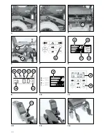
The blade-type fuse for the battery cur-
rent is located in the fuse holder under
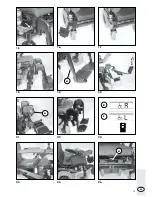
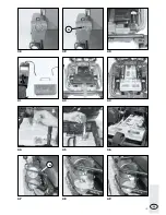
the seat (A, Fig. 5).
Pulling out the main fuse during driving
causes an immediate stopping of the
wheelchair! – Danger of accidents!
SPRINT GT, model 2.593
Main fuse for 6 and 10 km/h versions:
60 amp maxi-fuse (light-blue, blade-
type).
FAULT CLEARANCE
FAULT CLEARANCE
If treated properly, your wheelchair will
not malfunction. To ensure that your
wheelchair gives you many years of
service, especially if it is your first elec-
tronic wheelchair, we have listed possi-
ble faults and remedial action to be tak-
en in the following table.
We recommend that an inspection is
carried out every 2 years to permit the
early recognition and clearance of faults
which are not listed in the table. The
following inspection certificates should
then be stamped by your specialist deal-
er.
!
Attention:
Work on the internal mechanics of
the joystick and electronic parts
should only be carried out by a spe-
cialist workshop .
The mechanics of the joystick should
never be oiled but completely re-
placed!
Other blade-type fuses
The following blade-type fuses are lo-
cated in a row on the adapter board in
the adapter box (A, Fig. 54):
– 20A charging fuse
– 2A
power electronics control
– 7,5A electrical adjustment
– 5A
lighting
Battery charging fuse
Charging fuse located in the control box
15A ø6x32mm miniature fuse (glass
tube).

