MFJ-249D Instruction Manual
HF/VHF SWR Analyzer
4
2.5
“Power Saving” Mode (sleep mode)
The analyzer's current drain is normally around 150 mA, which places a moderate demand on the battery pack. You
can extend the analyzer's running time significantly by using the internal
Sleep Mode
power-saving function. In
Sleep
Mode
, the analyzer's RF-generator shuts down and battery drain drops to under 15 mA. Any time
Sleep Mode
is
activated, the analyzer
operates with a
two-minute inactivity window
.
During any 2-minute period, you must actuate
the Mode switch -- or adjust the frequency by more than 50 kHz -- at least once for the analyzer to remain awake.
Any time a two-minute inactivity period elapses, the power saving circuit automatically switches in. When the
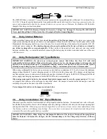
analyzer goes to sleep, a blinking
SLP
message will appear in the display’s lower right corner, as shown below:
To reawake the unit, momentarily press either the
Mode
or
Gate
button.
To Disable
Sleep
mode:
(1.) Turn the analyzer off.
(2.) Press and hold the
Mode
button while reapplying power.
(3.) Continue holding the
Mode
button until the copyright message appears on the screen.
(4.) Release
Mode
. If
Sleep Mode
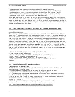
was disabled successfully, the message shown below will appear on-screen.
The
Sleep Mode function becomes re-enabled anytime the analyzer is turned Off and On again
.
3.0 MAIN MENU AND DISPLAY
IMPORTANT WARNING: Never Apply RF or any other external voltage to the Antenna port of this
unit. The MFJ-249D uses zero bias detector diodes that may be damaged by external voltages. Read
Section-2.0 before applying power! Incorrect supply voltages will also damage this unit.
3.1
General Connection Guidelines
1.) Antenna Jack:
When making RF measurements, connect your
Device Under Test
(DUT) to the SO-239
connector located on the top of the case. You'll use this port for
SWR
and all other RF measurements excluding the
Frequency Counter
function.
2.) Power connector
: (2.1 mm type) is described in Section 2.0. Be sure to read Section-2.0
before
operating your
unit. Using an incorrect power sources can permanently damage the analyzer.
3.) Frequency Counter Input
: BNC connector used for frequency-counter functions only.
3.2
Power-up Display
After turning on the
Power
switch (or after applying external power with the switch on), a sequence of three message
screens appear on the display.
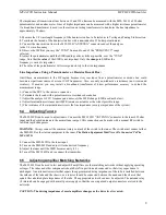
The first screen presents the analyzer's software version (
VER)
.
MFJ-249D
VER 13.40
Summary of Contents for MFJ-249D
Page 1: ......


