MFJ-1775 Rotatable Mini-Dipole
Instruction Manual
10
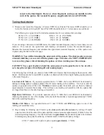
20 M: 1" trimmed off a pair of spokes equals
approximately
100 KHz
15 M: 1" trimmed off a pair of spokes equals
approximately
175 KHz
10 M: 1" trimmed off a pair of spokes equals
approximately
250 KHz
Note:
Typical final spoke lengths for the low end of each HF band are shown in the table on the next
page.
3) If the SWR is acceptable at the desired operating frequency, the adjustment for that band may be
skipped.
4) Now tune progressively higher frequency bands by trimming pairs of spokes on each of the two
loading coil assemblies. Keep each pair of capacitance spokes equal in size. 20 meters must be the
second HF band adjusted, 15 meters the third, and 10 meters last. After adjusting 10 meters go back
and check the other bands. Re-check the tightness of all spoke screws.
5) The six and two meter bands are tuned by lengthening or shortening the threaded portion of the stubs.
This adjustment is very coarse. If the frequency is still too low with the stub element extension at a
minimum, the unthreaded ends of the stubs can be trimmed. Once again the lower frequency stub (6
meters) should be adjusted first.
NOTE
: The six meter stub covers from 50 to 54 MHz as it is adjusted. Be careful because the third
harmonic resonance of the six meter stub will show up as a low SWR on the third harmonic of it's
setting, usually between 150 and 160 MHz. The range of the two meter stub allows frequencies as
low as 130 MHz to be covered with the stub fully extended and 148 MHz with the stub fully
contracted.
NOTE:
The 2-meter resonance is affected by other resonances in the overall antenna structure. You
may find a fixed resonance close to the 2-meter band that has a very low SWR, but the resonant
frequency of this resonance will not be adjustable. Ignore this point and look for a higher SWR
resonance that
is
adjustable. Typically, you may find a fixed, low SWR resonance at 144 MHz, and
an adjustable resonance at 147 MHz with a 2:1 SWR. This higher frequency, higher SWR resonance
is the desired resonance point. Note that between these two resonant points, the SWR should be 2:1
or less across most of the 2-meter band.
6) Final frequency adjustments can be made by trimming spokes on one of the loading coil assemblies
only if desired, though symmetrical trimming is preferred. The minor adjustment of one side only
without the symmetrical trimming of the other side is perfectly acceptable so long as the frequency is
changed less than 30 KHz on 40 meters and 60 KHz on the higher bands during final adjustment.
Moving the resonant frequency too far with only the spokes on one loading coil assembly will
increase the SWR of the antenna at the resonant frequency.
NOTE:
The spokes can also be bent toward another spoke
in the same mounting ring
to raise the
frequency slightly without cutting.
7) When all tuning is complete, install the plastic end caps on the outer ends of all spokes. Note that the
plastic end caps will lower the resonant frequency on all HF bands by 30-50 kHz. The plastic end
caps should fit snugly on the spokes. Should a cap fit too loosely, add a drop of glue to the spoke
end before sliding on the cap.


