MFJ-1775 Rotatable Mini-Dipole
Instruction Manual
6
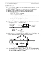
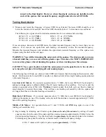
7) Slide the 1-1/8 x 60” aluminum radiator tubes over the center insulator/balun assembly with the
slot on each aluminum tube on the topside of the fiberglass rod/balun assembly. Insert the ¼-20
bolts through the aluminum tube/fiberglass assembly and through the balun lugs. Add the ¼-20
split lock-washers and nuts and tighten securely. See Figure 3.
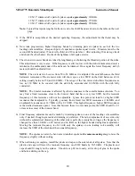
8) Slide four hose clamps over each aluminum tube. Slide two hose clamps (one on each aluminum
radiator tube) up against the ¼-20 hardware and clamp the four aluminum stub channel brackets
(two on each radiator) on opposite sides of the aluminum radiator tubes as shown in Figure 4.
9) Using eight hose clamps (four on each radiator), clamp the fiberglass insulators so as to support
the 16” and 55” threaded rods. Position the insulators as shown in Figure 4.
10) Mount the four stubs by threading a 10-32 x 3/8" nut 1/2" near the end of the threads. Add a
second nut and lock-washer to sandwich the bracket between the two nuts, leaving no more than
¼” of threaded rod exposed beyond the aluminum bracket. See Figure 4.
IMPORTANT: Use a 5/16” nut driver to tighten the capacitance spokes in place. Tighten
by hand only. A high torque electric screwdriver will shear the screws.
Figure 3: Radiator Tube Assembly – Top View
Fiberglass Rod
Balun wire
(2 plcs)
Slot
¼-20 hdwr
(2 plcs)
AL Radiator (2 pcs)
Balun
¼-20 hdwr
(end view)
~3”
~20”
Balun
Figure 4: 6 and 2-meter stub assembly and mounting
~35”
~11”
AL brkt
Fiberglass brkt
Fiberglass brkt
AL brkt
#10 nuts (2),
LW (1) – 4 plcs


