MFJ-1775W Rotatable Mini-Dipole
Instruction Manual
6
7)
Slide one hose clamps over each aluminum tube.
IMPORTANT: Use a 5/16” nut driver to tighten the capacitance spokes in place. Tighten
by hand only. A high torque electric screwdriver will shear the screws.
8)
Install the 6-32 screws in all rings of both loading coil assemblies, loosely holding them in place with
their associated nuts. Position the screws so the threaded ends of the screws are pointed outward
towards the two ends of each loading coil assembly as shown in Figure 5. .
NOTE: You can ease your tuning effort by pre-marking the outer ends of the spokes prior
to installation. You can do this by placing 1”, 2”, and 3” marks on one end of each
spoke using a black permanent marker pen. Then subdivide these marked
sections into ¼” segments using a red permanent marker pen.
NOTE: Install the spokes through the rings until they come in contact with the fiberglass
rod. This will give you about 1/4” of spoke available to slide back out should you
trim too much off a spoke during tuning.
9)
Install six
36.75”
spokes in the 60-meter rings of both loading coil assemblies. With a 5/16” nut
driver, tighten the nuts until the spokes are snug.
10)
Install 2
40.75”
spokes in the remaining locations on 60-meter rings of both loading coil assemblies.
With a 5/16” nut driver, tighten the nuts until the spokes are snug.
11)
Install four
36.75”
spokes in the 30-meter rings of both loading coil assemblies. With a 5/16” nut
driver, tighten the nuts until the spokes are snug.
12)
Install four
18.75”
spokes in the 17-meter rings of both loading coil assemblies. With a 5/16” nut
driver, tighten the nuts until the spokes are snug.
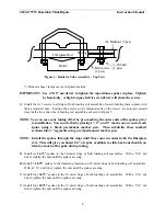
Figure 3: Radiator Tube Assembly – Top View
Fiberglass Rod
Balun wire
(2 plcs)
Slot
¼-20 hdwr
(2 plcs)
AL Radiator (2 pcs)
Balun

