background image

MFJ-1778 G5RV Multiband Antenna


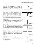
30 meter band: 

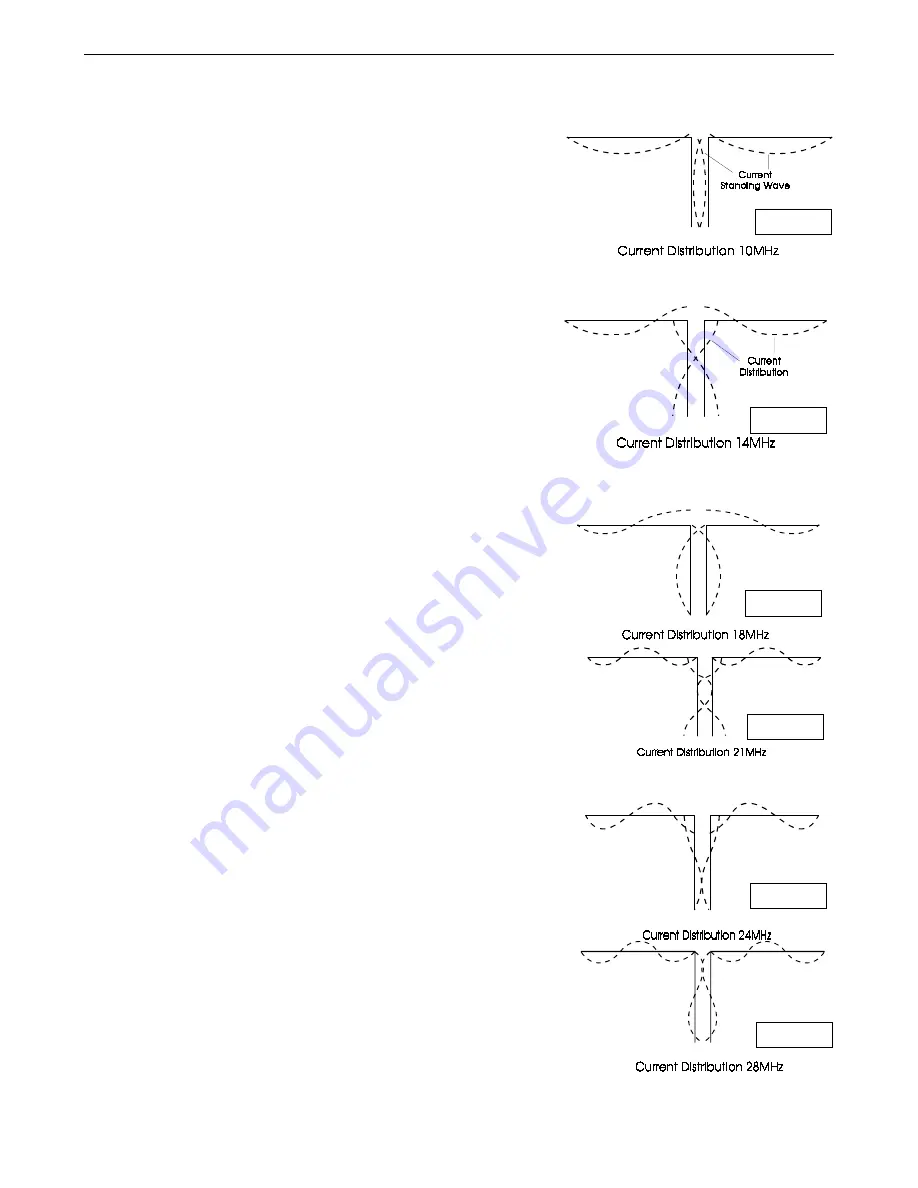
On 30 meters the MFJ-1778 (G5RV) functions as an extended 
double zepp.  The current distribution of the antenna and 
matching line is shown in figure 3.  The horizontal radiation 
pattern is similar to the pattern of the 40 meter band (broadside) 
but has four additional minor lobes.  The antenna has a gain of 
around 3 dB on 30 meters. 
 

20 meter band: 

This is the true design frequency of the MFJ-1778.  The 
antenna is a 3/2 wave center-fed antenna and has a multi-lobe 
pattern on this band.  On this band the G5RV is a good DX 
antenna at heights of 30-60 feet.  The radiation angle is fairly 
low.  The feedpoint of the antenna is approximately 100 ohms 
resistive, and the ladder line functions as a 1:1 ratio 
transformer.  See figure 4 for a digram of current distribution. 
 

17 meter band: 

The antenna is a pair of full-wave antennas fed in-phase on this 
band.  The radiation angle of the antenna is low with many 
lobes in all directions.  The current distribution of the antenna 
and matching line is shown in figure 5. 
 

15 meter band: 

The antenna is a pair of 1.1 wavelength long wires fed in-phase on 
this band.  This pattern is multi-lobed in the horizontal plane with 
a low radiation angle.  The current distribution of the antenna and 
matching line is shown in figure 6. 
 

12 meter band: 

On 12 meters this antenna is a pair of 1.3 wavelength longwires 
fed in-phase.  The feedpoint resistance is fairly low.  The 
radiation pattern has many lobes and a low radiation angle.  The 
current distribution of the antenna and ladder line is shown in 
figure 7. 
 

10 meter band: 

The MFJ-1778 functions as two 3/2 wave longwire antennas fed 
in-phase on this band.  The pattern has multiple lobes in all 
directions.  The current distribution of the antenna and matching 
line is shown in figure 8. 


Figure 3


Figure 4


Figure 5


Figure 6


Figure 7


Figure 8


Summary of Contents for MFJ-1778 G5RV

Page 1: ......

Page 2: ...and 2 15 meter band 2 12 meter band 2 10 meter band 2 160 meter band 3 Tools And Time Requirements 3 Safety Precautions 3 Installing The Antenna 4 Horizontal Antenna 4 Inverted V Antenna 4 Sloper Ante...

Page 3: ......

Page 4: ...antenna to eliminate or reduce the undesirable parallel feedline currents Failure to use a choke balun may result in RFI RF feedback or other symptoms of RF in the shack The Balun Requirement section...

Page 5: ...tenna is a pair of full wave antennas fed in phase on this band The radiation angle of the antenna is low with many lobes in all directions The current distribution of the antenna and matching line is...

Page 6: ...avy sinker to place a small line over a tree A larger line is then pulled up and used to pull the support rope over the tree The ARRL Antenna Handbook has detailed suggestions for installing wire ante...

Page 7: ...for example PVC pipe standoff supports 6 long Use nylon cable ties to secure the feedline to the supports NOTE An example of how to mount this antenna horizontally using two trees is shown in figure...

Page 8: ...ting element The feedline should be kept as vertical and as clear of metallic objects as possible The preferred method of 160 meter operation is to connect the antenna s shorted feedline conductors to...

Page 9: ...educe or eliminate parallel currents on the outside of the coax shield This will prevent or reduce RFI RF feedback RF burns and other effects of excessive RF in the station The best balun for this ant...

Page 10: ...ns These considerations are discussed in the 160 Meter Operation section Never use woven flexible braiding for ground connections unless absolutely necessary Braiding has high resistance to RF and lig...

Page 11: ...t check the appropriate section of this manual If the manual does not reference your problem or your problem is not solved by reading the manual you may call MFJ Technical Service at 601 323 0549 or t...

Page 12: ...x Parc d Activit 205 rue de l Industrie 77176 SAVIGNY lE TEMPLE FRANCE T l 33 01 64 41 78 88 Fax 33 01 60 63 24 85 S A au Capital de 1 000000 F RC PARIS 787 350016 APE 322A CCP 35 79565 x LA SOURCE N...

Page 13: ...nt normalement l int rieur Figure B 15 5 rn isolateur corde piquet_V L MFJ 1778 G5RV ANTENNE MULTIBANDE 31 m V fil __ TWTn 450 Ohms ti 9 9 m 1 p _ coax 50 ohm l coup 1 1 Lfros H transe Poulie 15 5 m i...

Page 14: ...0 m l antenne est pratiquement omnidirectionnelle et a un grand angle de d part Bande des 40 M tres Fonctionne sur cette bande en deux demis ondes en phase avec un transformateur d imp dance en 4 Le r...

Page 15: ...e L angle de rayonnement est bas avec plusieurs lobes dans toutes les directions Point particulier pour le 160 M tres Possibilit de fonctionner en 160 m tres en utilisant 1 2 G5RV en antenne marconi P...

Reviews: