background image

Introduction

Thank you for purchasing the MFJ-1835H five band HF antenna.   You new antenna is composed of 
High strength material for excellent rigidly and light weight.  The MFJ-1835H is compact and excellent
for restricted space or portable installations.  The antenna is omnidirectional enough to not require a 
rotator.  It has good bandwidth and minimum SWR on all five bands.  It can be mounted on tripod for 
temporary locations or any mast 1-1/2 diameter or smaller for permanent installation. 

Preparation

This antenna although it is not heavy, might be cumbersome for one person to handle.  
It is a good idea to have a temporary mast about 6 feet off the ground to hold the antenna while you
are working on it.  If you don’t have a mast available, saw horses other support can be used.  
The antenna support arms can be installed on a flat surface like a garage floor if needed.  The antenna
assembly will go quickly and is fairly easy but take your time anyway.  As with all antennas, safety 
glasses are recommended during the assembly and tuning.  We don’t want you to “Poke your eye out”. 
Pick a clear open spot and assemble the antenna away from other people.  Do not allow children 
in the assembly area.  Only the people involved in the construction should be near.  If you plan to 
assemble the antenna over grass, be prepared to go on a lawn safari to find the hardware that you drop.
It’s not a question of if, but when you drop something.  A few extra parts have been included in the parts
pack for just such a adventure.   Assembly can be done by one person but when the antenna is to be 
mounted or moved, plan to have a friend help.  It is not wise to attempt to install any antenna without 
help.  Don’t rush.  The more time you put into the antenna, the happier you will be with  the results.  

WARNING

KEEP THIS ANTENNA  

AWAY FROM POWER LINES

Never mount or move any antenna where it can come into contact

with power lines.  If this antenna comes into contact with power 

lines, it can KILL you.  Never mount any antenna where if it fell

it could come into contact with power lines. 

Summary of Contents for MFJ-1835H

Page 1: ...ons Before Operating Equipment 300 Industrial Park Road Starkville MS 39759 USA Tel 662 323 5869 Fax 662 323 6551 COPYRIGHT 2015 MFJ Enterprises Inc C MFJ 1835H 10 12 15 17 20 METER INSTRUCTION MANUAL...

Page 2: ...y but take your time anyway As with all antennas safety glasses are recommended during the assembly and tuning We don t want you to Poke your eye out Pick a clear open spot and assemble the antenna aw...

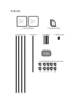
Page 3: ...In the box 2 mounting plates 1 mounting bracket 4 element arms 1 feed arm 5 insulators 1 matching box Parts pack 2 rolls of element wire for each band Lots of Nuts and Bolts 10 12 15 17 20...

Page 4: ...e sure the nuts are on the bracket side 4 places mounting bracket holes Select one of the four element arms Install the arm between the two plates using four 6 32 x 1 inch screws and nuts Snug the nut...

Page 5: ...e using the last two holes in the plate It does not matter which end you use The hole patterns are the same These holes are under the mounting bracket but it is not shown in this diagram Feed arm moun...

Page 6: ...ng plates Wind 12 turns of coax with a six inch diameter or install equivilant balun Mounting plate Mounting plate Now would be a good time to mount the antenna on a temporary mast if you haven t alre...

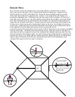
Page 7: ...t of slack in the wire Do not tighten the wire to remove sag A little sag will not hurt the performance of the antenna and it will prevent stress to the element wire and support arms when icing or str...

Page 8: ...t frequency This location will be the highest frequency This location will be between the two EXAMPLE Remember that It is not necessary to add the strips if the antenna is already at the frequency you...

Page 9: ...will cut down on the weight of the insulators Note that there are extreme high voltages present at the tips of the wires and arcing may occur while transmitting if the wire is frayed S Loop around th...

Page 10: ...In addition the coaxial cable feeding the antenna should have the shield grounded to eliminate the risk of any indoor equipment failure from allowing hazardous voltages from appearing indoors and crea...

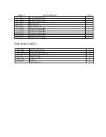
Page 11: ...meter wire assembly 12 meter wire assembly 15 meter wire assembly 1 1 2 2 2 17 meter wire assembly 13 1835 20 20 meter wire assembly 2 2 Parts Pack 17 1835 1 13 1835 17 656 0375S 705 0632 NL 561166 6...

Reviews: