background image

3

Permanent Installation

The ideal installation is a rigid pole or roof mount that puts the antenna completely
in the clear.  If the ideal installation is not possible,  choose the best compromise.
TV mast, heavy-duty rigid electrical conduit, and steel water pipes are suitable 
mast materials.  The use of soft or thin wall mast is not recommended. 

Portable Operation

The MFJ-1890 may be easily transported to temporary locations for portable, 
emergency, and contest operation.  Even for temporary or portable operation, do not
be casual about selecting a suitable mast.  If the antenna falls, it can be damaged and
may cause serious injury.  Whatever type of installation you choose, remember that
the antenna should be installed where it cannot be contacted by people or animals or 
come in contact with power lines.

Antenna Assembly

Assemble the antenna on a flat level surface.  Avoid assembly over grass as you may 
drop some of the parts and never find them again.   You may use a couple of saw horses 
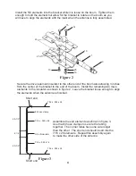
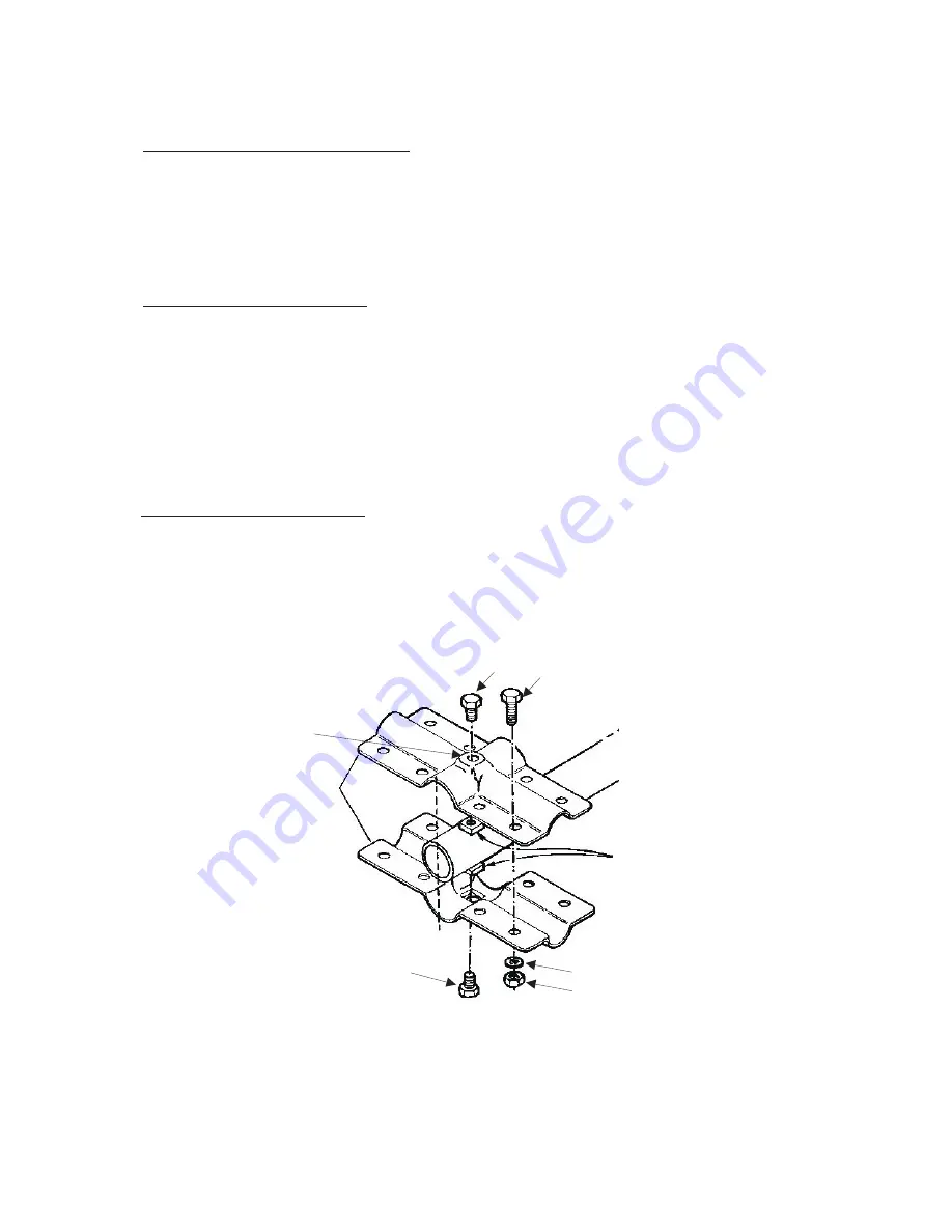
or other means of support to aid assembly.  Loosely assemble the #1 and #11 brackets
using the 1/4-20 nuts, bolts and washers as shown in figure 1.   Don't forget the square 
nuts that go inside the brackets.   The square nuts are different for each bracket and also
take different bolts.

Figure 1

24

14

22

25

16

24

19

This hole should be 3 inches 
from the end of the boom

Summary of Contents for MFJ-1890

Page 1: ...ctions Before Operating Equipment 300 Industrial Park Road Starkville MS 39759 USA Tel 662 323 9715 Fax 662 323 6551 COPYRIGHT 2012 MFJ Enterprises Inc Rev 1A C MFJ 1890 2 Element Moxon Beam for 10 me...

Page 2: ...ing a location For best performance on receiving and transmitting mount the antenna in a clear location above or away from buildings towers feedlines utility wires and other antennas While your own in...

Page 3: ...falls it can be damaged and may cause serious injury Whatever type of installation you choose remember that the antenna should be installed where it cannot be contacted by people or animals or come i...

Page 4: ...to hold the element but allow for the bracket to rotate on the boom as you will have to align the elements with the mast when the antenna is fully assembled 21 25 16 15 10 1 9 14 15 4 3 8 x 9 insulato...

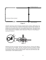
Page 5: ...ents Install the u bolt on the boom Place the 1 1 4 end caps on each end of the boom Figure 4 Figure 5 Short side on Driven element Driven element Reflector element Attach the feed line to the driven...

Page 6: ...6 1 4 20 1 2 28 1 2 74 5 8 55 1 4 173273 5 8 x 53 1 4 7 16 x 028 x 26 7 16 x 028 x 18 7 16 x 028 x 26 3 8 x 9 3 3 long end of corner Figure 6 6 DIRECTION OF RF ENERGY DRIVEN ELEMENT REFLECTOR ELEMENT...

Page 7: ...rate efficiently without the requirement of an earth ground safety grounding must still be provided to protect equipment property and persons from the hazards fo lightning strikes and other weather re...

Page 8: ...swaged Tube Boom 1 1 4 058 x 61 1 4 Drilled Tube 7 16 x 028 x 26 slotted Tube 7 16 x 028 x 18 slotted Tube 3 8 corner Rod Fiberglass 3 8 x 9 Balun Assembly Bracket 11 Bracket 1 Parts Pack MFJ 1890 Ho...

Page 9: ......

Page 10: ...oforeaves byeyebolts Applyroofing compound around thebase ofthebracket screws andevebolts formoisture sealino TELESCOPING MAST Guywiresshouldbeequally spacedinat leastthreedirections Useat leastthreeg...

Page 11: ...NOTES...

Page 12: ...ho attempt to repair defective units Technical consultation is available by calling 601 323 5869 5 This warranty does not apply to kits sold by or manufactured by MFJ Enterprises Inc 6 Wired and teste...

Reviews: