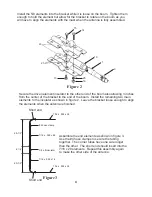
Secure the driven element insulator to the other end of the boom also allowing 3 inches
from the center of the bracket to the end of the boom. Install the remaining two main
elements to the insulator as shown in figure 2. Leave the bracket loose enough to align
the elements when the antenna is finished.
Figure 2
Install the 5/8 elements into the bracket while it is loose on the boom. Tighten them
enough to hold the element but allow for the bracket to rotate on the boom as you
will have to align the elements with the mast when the antenna is fully assembled.
21
25
16
15
10
1
9
14
15
4
3/8 x 9 insulator
#4 hose clamp
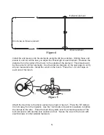
Assemble the end elements as shown in figure 3.
Use the #4 hose clamps to secure the tubing
together. The corner tubes have one side longer
than the other. The short end should insert into the
7/16 x 20 elements. Repeat this assembly again
to make the other side of the antenna.
Short end
Figure 3
Short end
7/16 x .028 x 26
7/16 x .028 x 26
7/16 x .028 x 18
7/16 x .028 x 26
28-1/2”
6-1/4”
20-1/2”
20
Summary of Contents for MFJ-1890
Page 9: ......
Page 11: ...NOTES...


