5
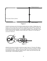
Install the end pieces onto the elements using the #4 hose clamps. Sliding these end
pieces in and out will be how you adjust the final length of each element. Measure the
distance from the center of the boom to the outside of the element. This distance will
be the same for all four elements. Use the antenna diagram on the next page to verify
all your measurements. Install the u-bolt on the boom. Place the 1-1/4 end caps on
each end of the boom.
Figure 4
Figure 5
Short side on Driven element
Driven element
Reflector element
Attach the feed line to the driven element as shown in figure 5. Place the 5/8 clamps
3/4 inch away from the insulator. Use the 10-24 bolts nuts and lock washers to tighten
the clamps to the tube. Place the feed line eyelets over the remaining section of the
bolt and secure with another lock washer and nut. Secure the coax to the boom with
electrical tape or other suitable fasteners.
3/4”
23
18
17
Summary of Contents for MFJ-1890
Page 9: ......
Page 11: ...NOTES...


