MFJ-933C
High-Efficiency Magnetic Loop Tuner
Instruction & Technical Manual
chosen frequency
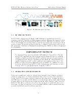
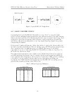
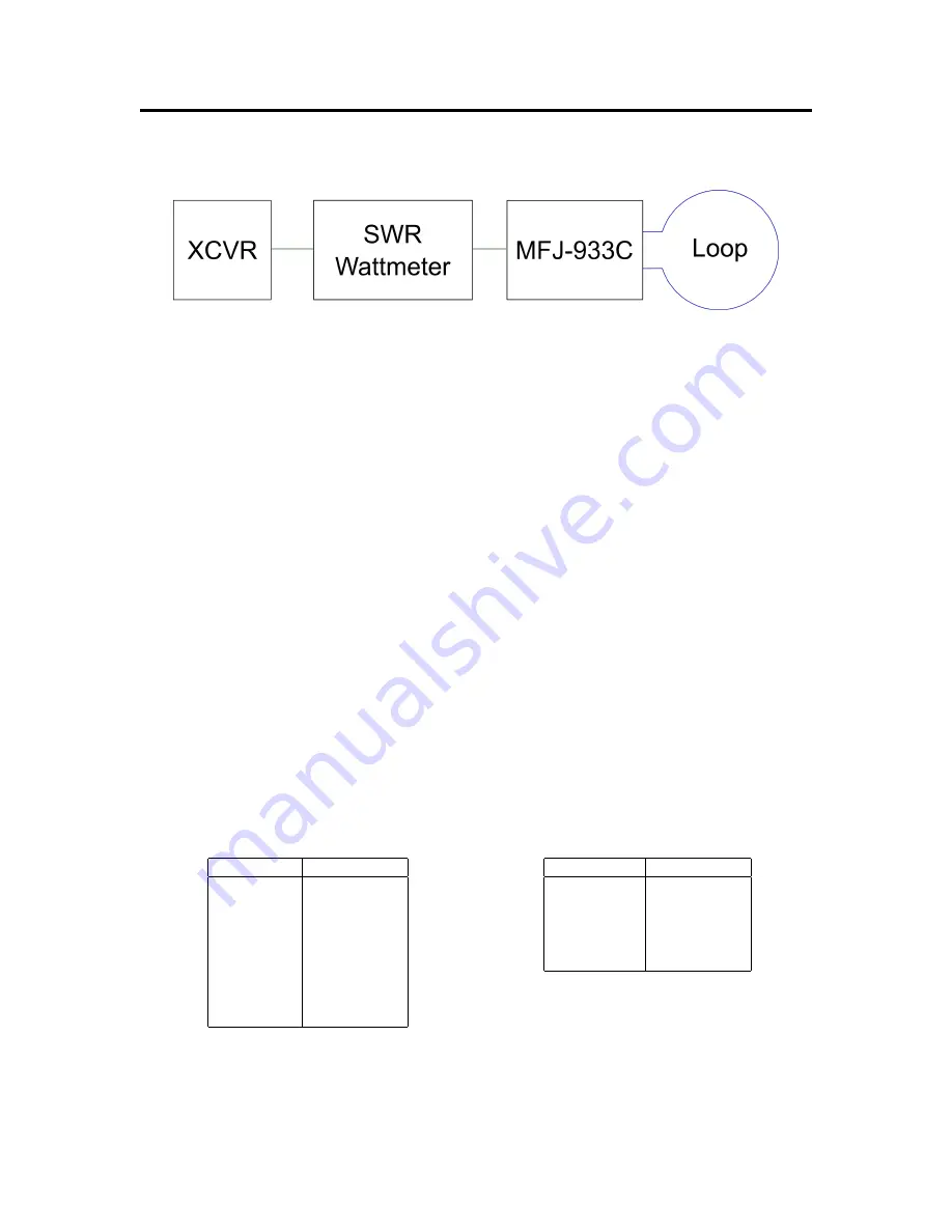
Figure 6: Typical MFJ-933C Configuration
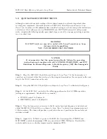
4.2
LOOP CONSTRUCTION
Constructing the loop for the MFJ-933C
High-Efficiency Loop Tuner
™
is reasonably simple.
Table 3a lists the maximum tunable lengths for the most efficient operation at the upper frequency
limit of each band, and Table 3b list the loop lengths for the move convenient band coverage. Each
length can be tuned lower in frequency. Exact frequency coverage depends on each individual
installation configuration involving choice of wire, loop length, loop shape, height above ground,
and operating environment.
The loop can be constructed from wire, tubing, sheet metal, or coaxial cable. An especially good
material is one-inch-wide PCB board. However, finding a piece of PCB board long enough to form
into a circular loop for 7.175 MHz may prove to be difficult! This leads us to the unique
opportunity to
experiment
while using the MFJ-933C
High-Efficiency Magnetic Loop Tuner
™
to
match the loop antenna you design.
The applications and parameters can be adjusted easily with the help of the freeware programs
previously mentioned, and you may choose to design a totally new and unique loop antenna for
on-air experimentation. Designing an outdoor loop for a band such as 7 MHz could be a challenge
yet result in a very good radiator and especially good receiving antenna for DX-ing and
rag-chewing. We at MFJ think the experimental aspects of the MFJ-933C are exciting, and can
provide hours of quality operating, even at QRP levels.
Table 3: Efficient Loop Length Estimates
(a) Single Band
Band (m)
Length (ft)
80
63.0
40
28.0
30
20.0
20
13.0
17
9.0
15
7.0
12
5.5
10
4.0
(b) Multi Band
Bands (m)
Length (ft)
40 – 30
20.0
30 – 20
13.0
30 – 17
9.0
20 – 15
7.0
17 – 10
4.0
-11-
Summary of Contents for MFJ-933C
Page 18: ...USER NOTES ...


