background image

MFJ-933C

High-Efficiency Magnetic Loop Tuner

Instruction & Technical Manual

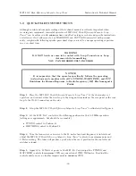
Step 4

Set the controls to the following positions:

TUNING control to Position 0.

MATCHING control to Position 10.

Step 5

Tune the transceiver to the desired frequency then adjust the controls for maximum noise

and S-Meter reading. The tuner will produce a peak in both when the proper positions for the
controls are achieved. The recommended process consists of the following steps:

Slowly rotate the TUNING control clockwise while listening for a peak until you reach
Position 5.

If no peak is found, re-position the TUNING control to Position 0.

Rotate the MATCHING control counter-clockwise one step to Position 9.

Slowly rotate the TUNING control clockwise while listening for a peak until you reach
Position 5.

If no peak is found, re-position the TUNING control to Position 0.

Rotate the MATCHING control counter-clockwise one more step to Position 8.

Slowly rotate the TUNING control clockwise while listening for a peak until you reach
Position 5.

Repeat this sequence until the MATCHING control reaches Position 0.

If no peak is found, the loop length is incorrect for the frequency of interest. At this point
refer to Tables 3a and 3b for the most efficient loop lengths.

Once a peak is found, alternately adjust the TUNING and MATCHING controls until the
peak is maximized.

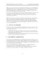
Step 6

Apply 10 to 20 Watts of power to the MFJ–933C and adjust the TUNING and

MATCHING controls for minimum SWR on your external SWR/Wattmeter. Readjust the
controls until you see no further improvement in minimum SWR.

Step 7

Once you are satisfied that the adjustments and settings are correct, you can increase the

power to 150 Watts if desired. Be sure that MPE distance standards as defined in Supplement B of
the FCC OET Bulletin 65, version 97-01 are met. Should any arcing be detected, stop
transmitting and check connections and proximity to objects that may be suspect. If arcing seems
to be inside of the MFJ–933C, lower the output power and re-check for arcing.

As a courtesy to our fellow hams, for safety, and to stay within FCC regulations you should use
the minimum power needed for communications. Power levels of 20 to 50 Watts often provide very
reliable communications. The difference between 50 and 100 Watts is less than

1

/

2

S-Unit and is

generally not noticeable on the receiving end.

Step 8

You can now enjoy operating in your favorite mode. However, if you change frequency

more than about 5 kHz, you may find you will need to re-adjust the TUNING controls for
minimum SWR. Rotate the TUNING control clockwise for higher frequencies and counter
clockwise for lower frequencies. Larger frequency changes can cause the MATCHING control to
also require adjustment. This concludes the MFJ–933C

High-Efficiency Magnetic Loop

Tuner

operating instructions.

-13-

Summary of Contents for MFJ-933C

Page 1: ...High Efficiency Magnetic Loop Tuner MFJ 933C INSTRUCTION MANUAL 2020 MFJ Enterprises Inc 300 Industrial Park Rd Starkville MS 39759 P 662 323 5869 F 662 323 6551 ...

Page 2: ...tional handbooks or other official publications The copy of this manual provided to the customer will not be updated to reflect current data Customers using this manual should report errors or omissions recommendations for improvements or other comments to MFJ Enterprises 300 Industrial Park Road Starkville MS 39759 Phone 662 323 5869 Fax 662 323 6551 Business hours M F 8 00 AM 4 30 PM CST ...

Page 3: ...S CONNECTIONS 8 3 LOOP THEORY 9 4 SYSTEM SETUP 10 4 1 CONFIGURATION 10 4 2 LOOP CONSTRUCTION 11 5 SYSTEM OPERATION 12 5 1 DETAILED OPERATION INSTRUCTIONS 12 5 2 QUICK START INSTRUCTIONS 14 5 3 MFJ 933C ACCESSORIES 15 6 TECHNICAL ASSISTANCE 15 List of Figures 1 An Electromagnetic Plane Wave 3 2 The Electromagnetic Spectrum 4 3 The MFJ 933C 7 4 Front Panel 8 5 Rear Panel 9 6 Typical MFJ 933C Configu...

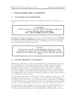
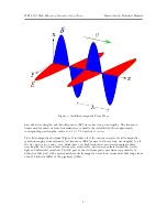
Page 4: ...elds Electromagnetic radiation is defined as waves of electric and magnetic energy moving together or radiating through space The movement of electrical charges generates these waves For example the movement of charge in a radio station antenna the alternating current creates electromagnetic waves that are radiated away from the antenna and intercepted by receiving antennas The term electromagneti...

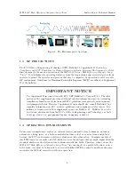
Page 5: ...rum Figure 2 includes all of the various energies of electromagnetic radiation ranging from extremely low frequency ELF ranges with very long wavelengths to all the way up to x rays and γ rays which have very high frequencies and correspondingly short wavelengths In between these extremes lie radio waves microwaves infrared radiation visible light and ultraviolet radiation The RF part of the elect...

Page 6: ... exposure to radio frequency electromagnetic fields However Supplement B users should also consult Bulletin 65 for complete information on FCC policies guidelines and compliance related issues Def initions of terms used in this supplement appear in Bulletin 65 Bulletin 65 can be viewed and downloaded from the FCC s Office of Engineering and Technology s website at https www fcc gov general radio f...

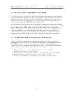
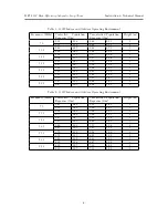
Page 7: ...re members of the general public always fall under this category when exposure is not employment related as in the case of residents in an area near a broadcast tower Neighbors of amateurs and other non household members would normally be subject to the general population uncontrolled exposure limits 1 6 OPERATING ENVIRONMENTS GUIDELINES Tables 1 and 2 list various MFJ 933C High Efficiency Magneti...

Page 8: ...0 93 4 06 1 23 1 3 07 0 93 4 95 1 50 3 24 0 3 23 0 98 5 48 1 66 1 3 37 1 02 5 51 1 67 3 28 0 3 47 1 05 6 04 1 83 1 3 47 1 05 6 04 1 83 3 Table 2 150W Indoor and Outdoor Operating Environment Frequency MHz Controlled Population Exposure ft m Uncontrolled Population Exposure ft m Height m 7 0 1 45 0 44 2 05 0 62 1 1 52 0 46 3 00 0 91 3 10 0 2 28 0 69 3 00 0 91 1 2 77 0 84 3 66 1 11 3 14 0 2 87 0 87 ...

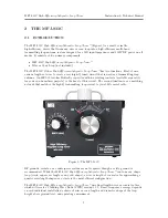
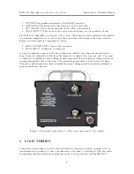
Page 9: ... with no rotating contacts available separately for your own homebrew projects is the heart of this circuit The second function is as a matching network that matches the high Q transmitting loop circuit to your 50Ω coaxial cable Figure 3 The MFJ 933C RF grounds radials or a counterpoise system are not required though a safety ground is recommended While the MFJ 933C High Efficiency Magnetic Loop T...

Page 10: ...l modes Easy Carry Handle Permits easy handling to from portable location s Frequency Coverage 60 10 meters 5 33 29 7 MHz Small Physical Profile 5 75 wide 8 75 deep by 4 25 tall Low Radiation Angle Rivals full size dipoles Quiet Reception Extremely quiet receiving antenna High Q design rejects out of band interference and harmonics and reduces overloading Indoor Use Perfect for apartments hotel ro...

Page 11: ...er A wire loop antenna connects to the Loop Connectors with the two wing nuts provided on the Loop Connector standoff rods RF from the transceiver is input at the rear coax port Care must be taken not to disturb the wires leading from the lugs on the Loop Connector stand off rods and entering through the back of the tuner The connection points must be kept clean at all times This unit is not inten...

Page 12: ...rent induced into a mirror image of the loop below the surface and the resistance of the image loop proportional to soil resistance Another loss component is due to current flowing in the soil via capacitance between the loop and soil surface These are all reduced by increasing the height of the MFJ 933C above the ground as measured from the tuner box An operational height equal to 1 2 the diamete...

Page 13: ...nding a piece of PCB board long enough to form into a circular loop for 7 175 MHz may prove to be difficult This leads us to the unique opportunity to experiment while using the MFJ 933C High Efficiency Magnetic Loop Tuner to match the loop antenna you design The applications and parameters can be adjusted easily with the help of the freeware programs previously mentioned and you may choose to des...

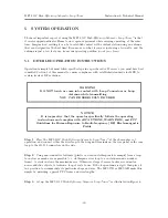
Page 14: ...ile transmitting YOU CAN BE SERIOUSLY INJURED NOTICE It is imperative that the operator specifically follows the operating instructions and complies with all CAUTIONS WARNINGS and FCC Guidelines for Human Exposure to Radio frequency RF Electromagnetic Fields Step 1 Place the MFJ 933C High Efficiency Magnetic Loop Tuner at the chosen place of operation and connect either the wire loop to the wing n...

Page 15: ...CHING controls until the peak is maximized Step 6 Apply 10 to 20 Watts of power to the MFJ 933C and adjust the TUNING and MATCHING controls for minimum SWR on your external SWR Wattmeter Readjust the controls until you see no further improvement in minimum SWR Step 7 Once you are satisfied that the adjustments and settings are correct you can increase the power to 150 Watts if desired Be sure that...

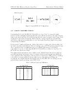
Page 16: ...ure to Radio frequency RF Electromagnetic Fields Step 1 Place the MFJ 933C High Efficiency Magnetic Loop Tuner at the chosen place of operation and connect either the wire loop to the wing nut terminals on the rear panel or the coax loop to the SO 239 connectors on the side Step 2 Setup the MFJ 933C High Efficiency Magnetic Loop Tuner as illustrated in Figure 6 Step 3 Set the MFJ 933C controls to ...

Page 17: ...Efficiency Magnetic Loop Tuner operating instructions 5 3 MFJ 933C ACCESSORIES Two kits are available for use with the MFJ 933C High Efficiency Magnetic Loop Tuner and each gives the operator expanded operational capabilities and use of pre made fabricated wires and equipment These kits are the MFJ 57B which contains a PVC Cross device for mounting a precut and lugged wire loop to the top cover of...

Page 18: ...USER NOTES ...

Reviews: