background image

VEC-820K Instruction Manual

CW Filter

INTRODUCTION

Thank you for purchasing the VEC-820K CW Filter kit. The VEC-820K consists
of a four stage, switch selectable band pass CW filter, using selected components
that will make "cleaning up" CW signals effortless and easy. With the VEC-
820K you bring up any hard to hear signal out of a "band pile up," for easy
listening, or get rid of unwanted, annoying signals. The VEC-820K also features
a headphone output that will allow the use of standard monoral headphones.
Although physically small in size, the VEC-820K is high on performance and
reliability. The VEC-820K is powered from a 9-volt transistor radio batterv.

TOOLS AND SUPPLIES

Construction Area: Kit construction requires a clean, smooth, and well-ighted
area where you can easily organize and handle small parts without losing them.
An inexpensive sheet of white poster board makes an excellent construction
surface. while providing protection for the underlying table or desk. Well-
diffused overhead lighting is a plus, and a supplemental highintensity desk lamp
will prove especially helpful for close-up work. Safety is an important
consideration. Be sure to use a suitable high-temperature stand for your soldering
iron. and keep the work area free of combustible clutter.

Universal Kit-building Tools: Although your particular kit may require
additional items to complete, virtually all construction projects require a work
area outfitted with the following tools and supplies:

Summary of Contents for VEC-820K

Page 1: ...re suitable Vectronics reserves the right to make substitutions at any time In most cases these changes will be clearly noted in an addendum to the manual Defective Parts Today s electronic parts are physically and electrically resilient and defective components are rare However if you discover an item during your pre construction inventory that s obviously broken or unserviceable we ll replace it...

Page 2: ......

Page 3: ...istor radio batterv TOOLS AND SUPPLIES Construction Area Kit construction requires a clean smooth and well ighted area where you can easily organize and handle small parts without losing them An inexpensive sheet of white poster board makes an excellent construction surface while providing protection for the underlying table or desk Well diffused overhead lighting is a plus and a supplemental high...

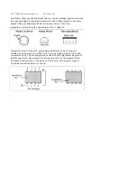
Page 4: ...mponent lead or pad Solder bridges form when a trail of excess solder shorts pads or tracks together see Solder Tips below 4 Omitting or Misreading a Part This is easier to do than you might think Always double check to make sure you completed each step in an assembly sequence Soldering Tips Cleanliness and good heat distribution are the two secrets of professional soldering Before you install and...

Page 5: ......

Page 6: ...ntation is indicated by the positioning of the cooling tab Integrated Circuits Proper IC positioning is indicated by a dot or square marking located on one end of the device A corresponding mark will be silk screened on the PC board and printed on the kit s parts placement diagram To identify specific IC pin numbers for testing purposes see the diagram below Pin numbers always start at the keyed e...

Page 7: ...ed by type and arranged by value ahead of time Use this inventory as an opportunity to sort and arrange parts so you can identify and find them quickly Qty Part Description Designation 6 24 3K ohm resistor red yellow orange brown R9 R10 R12 1 R12 R13 R14 4 681 K resistor blue gray brown orange R5 R6 R7 R8 4 1 82M ohm resistor brown gray red yellow RI R2 R3 R 4 8 1000 pF poly capacitor 1000J C1 C2 ...

Page 8: ......

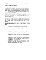
Page 9: ... step is complete and use the other for double checking your work before operation Important Note Capacitors Cl C8 are made of a polystyrene type material Avoid overheating these components when soldering to prevent melting the capacitor body 1 Locate capacitor C 1 1000pF This is a polystyrene capacitor and will be marked with a 1000P on the body actual value in pF 2 Mount C l and solder both lead...

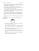
Page 10: ...arefully install C9 ensuring not to chip the ceramic material Once installed then solder in place 11 Locate resistor R1 This is a 1 82M resistor brown gray red N ellow brown Carefully bend the leads close to the resistor body to form right angles see following diagram 12 Insert RI into its mounting holes so the resistor body rests against the board Solder in place and trim the leads 13 Locate resi...

Page 11: ...fully bend the leads close to the resistor body as in Step 11 24 Insert R7 into its mounting holes so the resistor body rests against the board Solder in place and trim the leads 25 Locate resistor R8 This is a 681K resistor blue gray brown orange broL n Carefully bend the leads close to the resistor body as in Step 1 l 26 Insert R8 into its mounting holes so the resistonbody rests against the boa...

Page 12: ...to its mounting holes so the resistor body rests against the board Solder in place and trim the leads 37 Locate resistor R14 This is 24 3K resistor red yellow orange red brown Carefully bend the leads close to the resistor body as in Step 11 38 Insert R14 into its mounting holes so the resistor body rests against the board Solder in place and trim the leads Save the excess trimmed pieces of resist...

Page 13: ...silk screened 1 on the circuit board Solder in place and trim the excess lead 50 Take one 3 piece of insulated wire and insert one end into the hole silk screened 2 on the circuit board Solder in place and trim the excesslead 51 Take one 3 piece of insulated wire and insert one end into the hole silk screened 3 on the circuit board Solder in place and trim the excess lead 52 Locate the battery sna...

Page 14: ...rim the excess lead from the switch contact 63 Connect the other end of the insulated wire located at 1 on the circuit board at Point F on SW I Solder in place and trim the excess lead from the sNvtich contact 64 Cut a 1 1 4 piece of wire from one of the remaining 3 65 Using the wire strippers remove a 1 4 piece of the insulation from each end of the 1 1 4 wire 66 Connect the t t 4 piece of wire b...

Page 15: ...rack area If you suspect a solder bridge hold the board in front of a bright light for a better view All joints should be smooth and shiny indicating good solder wetting and flow Resolder any beaded or dullappearing connections If you find a construction error and need to remove a part or two it will be easier if you have the right tools One very convenient item for freeing soldered in parts is a ...

Page 16: ...he narrowest filter cutoff while the 180 hertz cutoff is the second position from the left and is the N idest filter cutoff Probably the best method of seeing if the VEC 820K is working or not is to listen to some on the air CW signals Then using SW1 select the filter cutoff position that best cleans up the signal being received If you are trying to pick one signal out of a very tight band pile up...

Page 17: ...on SW 1 Apply the negative side of the audio to the negative side of the battery snap Please refer to the Parts Placement section Figure 2 for the location of Point A on SW 1 Nest connect the POSITIVE lead of the external speaker to the NEGATIVE end of C11 Please refer to the Parts Placement section Figure 3 for the location of C 11 Connect the NEGATIVE lead of the external speaker to the point la...

Page 18: ...alled properly a wrong value part in place of another or a broken part A close inspection at this point will reveal some accidental mistake Intermittent Filter Operation A filter that operates intermittently may have poor solder connections a problem Nyith broken wires or low voltage power source Self oscillation may be caused b_v a defective U1 or U2 Also check for dirty or intermittent switch op...

Page 19: ...king good signal copying possible The center frequency is betNNeen 750 800 hertz The filter is able to drive an 8 ohm speaker or Specifications Bandwidth 80 Hz 110 Hz 180 Hz sNNitch Skirt Re_jcolon At least 60dB do Nn 1 octave from center frequency for 80 Hz bandxN ENCLOSURE Vectronics has designed a matching enclosure just for your CIF Audio Filler Kit The matching enclosure is an all includes kn...

Page 20: ......

Reviews: