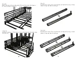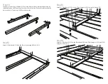
background image

• 

To reduce the risk of serious injury or death, you MUST read and 

follow these instructions before assembly and before use. 

• CONTINUOUS ADULT SUPERVISION IS REQUIRED.
• This unit is recommended for use by children 3-10 years of age. 
• Not suitable for children under 3 due to their inability to use safely. 
•  WARNING: ONLY FOR DOMESTIC USE. 
•  RESIDENTIAL HOME USE ONLY. This unit is not intended for public use. 

The manufacturer does not warranty this product if it is used for 
commercial purposes like daycare, schools, churches, nurseries or parks.

• Children must not use this product prior to complete assembly and 

inspection by a competent adult. The unit must be fully assembled, 
properly installed and anchored prior to use.

• WARNING! This toy produces flashes that may trigger epilepsy in 

sensitized individual. 

Installation over concrete, asphalt, dirt, grass, carpet and other hard 
surfaces creates a risk of serious injury or death from falls to the ground. 
Install and maintain shock absorbing material under and around this unit 
as recommended in this manual. 

Place this unit on level ground at least 6 ft. (2m) from any obstruction 
such as a garage or house, fences, poles, trees, sidewalks, walls, 
landscape timbers, rocks, pavement, planters, garden borders, 
overhanging branches, laundry lines, and electrical wires. 

ADULT ASSEMBLY REQUIRED. This product contains small parts and parts 
with sharp edges and points. Keep parts away from children until fully 
assembled. 

Choose a level surface for this equipment. This can reduce the likelihood 
of the unit tipping over and loose-fill materials from washing away 
during heavy rains. Stakes must be installed straight up and not at an 
angle. Ensure soil conditions are adequate to firmly hold the stakes.
DO NOT allow children to play on this unit until assembly is complete and 
the unit is properly anchored.

Owners are responsible for maintaining legibility of the warning labels.
Please remove the protective film on the signage and logo plate before use.

INSTRUCTIONS FOR SAFE USE

IMPORTANT SAFETY INFORMATION

WARNING:

WARNING:

SERIOUS HEAD INJURY HAZARD:

COLLISION HAZARD:

CHOKING HAZARD/ SHARP EDGES & POINTS:

WARNING LABEL:

STRANGULATION HAZARD:

TIP OVER HAZARD:

• NEVER allow children to play with ropes, clotheslines, pet leashes, cables, 

chains, cord-like items, or items with a cord or strap when playing on this 
unit. DO NOT attach these items or similar items to this unit. 

• NEVER allow children to play with the LED lights other than it is intended use. 
• NEVER allow children to wear loose-fitting clothing, such as, but not limited 

to: ponchos, hoods, scarves, capes, necklaces, items with draw-strings, cords 
or ties when playing on this unit.  Open-toe/open-heel footwear is not 
permitted. Children should wear well-fitting clothing and closed-toe shoes.

• NEVER allow children to wear bike or sports helmets when playing on this 

unit. Instruct them to remove these items before playing on this unit.

•    User safety is our  top concern. Read and understand the 

following statements and warnings to reduce the likelihood of 
serious or fatal injury. Review this information with your child 
and any other users.

1. ON-SITE, CONTINUOUS ADULT SUPERVISION IS REQUIRED FOR 

CHILDREN OF ALL AGES. Most serious injuries and deaths on 
playground equipment result when children are playing 
unsupervised. This product meets all applicable safety 
standards. Complying with all warnings and important 
information in this manual will reduce the risk of serious or 
fatal injury to children playing on this unit. Review all warnings 
and play information regularly with any child using this unit. 
Ensure children fully understand and follow these instructions. 

2. This unit is designed for a specific number of users whose 

combined weight should not exceed the capacity limitations of 
110 lbs. per child with a maximum of 4 children.

3. DO NOT allow children to use the equipment in a manner other 

than intended.

4. DO NOT climb or use the unit when it is wet. Wipe dry before 

use.

5. DO NOT jump from the deck or any part of the unit. Always use 

ladders and ramps. Standing on or jumping from elevated 
surfaces can be dangerous. 

6. DO NOT crawl or climb on the roof.
7. Verify that any suspended climbing rope, chain, or cable is 

secured at both ends and that it cannot be looped back on 
itself and create an entanglement hazard.

8. DO NOT attach items to the unit that are not specifically 

designed for use with the unit, such as, but not limited to: 
jump ropes, clotheslines, pet leashes, cables and chains, as 
they may cause a strangulation hazard.

9. Any modifications made to this product must be carried out 

according to these instructions.  Installation of included ropes, 
nets and other attached accessories must be fixed on all ends 
according to these instructions.

10. Never add extra length to chain or rope. The chains or ropes 

provided are the maximum length designed for the swinging 
elements. 

3

54

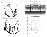
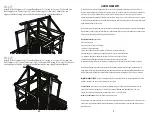
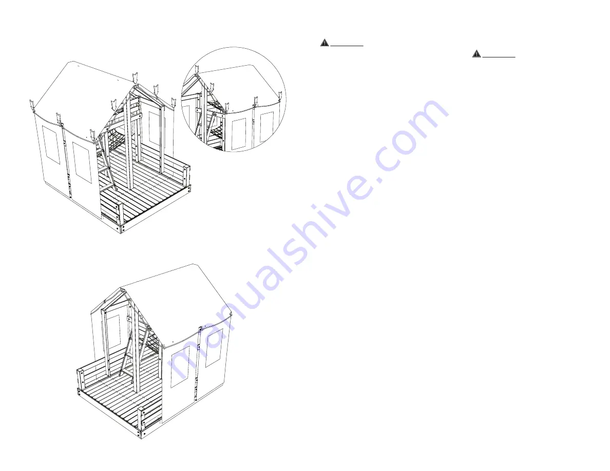
Step 83:

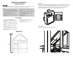
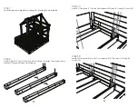
Attach the Light Box Strip (DL01) to the Tarp using the (9) ties attached to the Tarp.

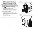
Step 84:

One week later tighten all the hardware.

Summary of Contents for Real Wood Glamping House 657511C3

Page 1: ...ries Alllogos names characters likenesses images slogans andpackaging appearancearethepropertyofLittleTikes PrintedinU S A 0421 0 C3 LittleTikesConsumerService 2180BarlowRoad Hudson Ohio44236U S A 1 800 321 0183 Please keep this manual as it contains important information THIS PRODUCT IS INTENDED FOR USE BY CHILDREN FROM AGES 3TO 10 CAPACITY 4 USERS MAXIMUM WEIGHT LIMIT 110 lbs 50 kg PER CHILD Gla...

Page 2: ...er reviewing the entire manual decide if you will need professional assistance assembling this unit Before beginning assembly separate and identify the contents of this unit to ensure you have all parts listed in this manual If you cannot find a part check the packing materials thoroughly as loose parts and small pieces may have shifted in transit If any part is missing or damaged contact LittleTi...

Page 3: ...ke items or items with a cord or strap when playing on this unit DO NOT attach these items or similar items to this unit NEVER allow children to play with the LED lights other than it is intended use NEVER allow children to wear loose fitting clothing such as but not limited to ponchos hoods scarves capes necklaces items with draw strings cords or ties when playing on this unit Open toe open heel ...

Page 4: ...verhang branches laundry lines or electrical wires Provide enough room so that children may play on this unit safely For example for structures with multiple play activities a slide should not exit in front of a swing Place this unit where adults are easily able to watch children at play UNIT POSITIONING RECOMMENDED SURFACING IMPORTANT SAFETY INFORMATION NOTE DO NOT install loose fill surfacing ov...

Page 5: ...s on a 6 inch depth of uncompressed shredded tire samples produced by four manufacturers The tests reported critical heights which varied from 10 feet to greater than 12 feet It is recommended that persons seeking to install shredded tires as a protective surface request test data from the supplier showing the critical height of the material when it was tested in accordance with ASTM F1292 Maximum...

Page 6: ...epths less than 6 inches the protective material is too easily displaced or compacted Use containment such as digging out around the perimeter and or lining the perimeter with landscape edging Don t forget to account for water drainage Check and maintain the depth of the loose fill surfacing material To maintain the right amount of loose fill materials mark the correct level on play equipment supp...

Page 7: ...ch season Inspect wood parts monthly The grain of the wood sometimes will lift in the dry season causing splinters to appear Light sanding may be necessary to maintain a safe play environment Treat your unit with stain regularly to help prevent severe splitting and other damage A waterborne transparent stain has been applied to your unit This is done for color only Once or twice a year depending o...

Page 8: ...terference in a residential installation This equipment generates uses and can radiate radio frequency energy and if not installed and used in accordance with the instructions may cause harmful interference to radio communications However there is no guarantee that interference will not occur in a particular installation If this equipment does cause harmful interference to radio or television rece...

Page 9: ...ion Laborforreplacementofanydefectiveitem s Incidentalorconsequentialdamage Cosmeticdefectswhichdonotaffectperformanceorintegrityofapartortheentireproduct Vandalism improperuse failureduetoloadingorusebeyondthecapacitiesstatedinthismanual Actsofnatureincludingbutnotlimitedtowind storms hail floodsorexcessivewaterexposure Improperinstallationincludingbutnotlimitedtoinstallationonuneven unlevelorsof...

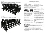
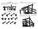
Page 10: ...driver Optionally you may need a Flathead Screwdriver 10 31 Bolt A1 26 Bolt A2 3 Bolt A3 31 Nut A1 26 Nut A2 3 Nut A3 12 Nut L1 23 Screw B1 24 Screw C1 276 Screw C2 18 Screw C3 18 Screw C4 9 Screw C5 47 Step 69 Attach 1 Roof Board C11 to the Tower Legs C01 L03 and L04 using 3 Screws B1 Ensure that the end with the overhang is placed over the Tower Leg C01 Step 70 Attach 1 Roof Support J1 to the Ro...

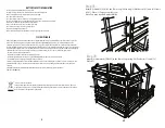
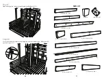
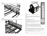
Page 11: ...port C10 2 Floor Support C20 3 Floor Support H1 11 2 Floorboard 01 14 Floorboard C14 2 Floorboard C15 1 Floorboard C16 1 46 Step 67 Stand and align the Ladder Assembly with the Rail Board C13 Step 68 Secure the Ladder Assembly to the Glamping House Assembly using 4 Brackets G1 and 24 Screws C1 ...

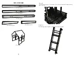
Page 12: ... C18 4 Ground Stake DD01 2 Hammock DW01 1 Handle LS01 3 Ladder Rung H2 1 Left Upright H4 1 Light Box DL01 3 Rail Board C06 2 Rail Board C07 1 Right Upright H3 45 Step 65 Attach 1 Rear Board C19 to the Ladder Assembly using 4 Screws C2 Step 66 Turn the Ladder Assembly over ...

Page 13: ...t J1 1 Tower Leg C01 2 Tower Leg C02 2 Tower Leg L01 1 Tower Leg L02 1 1 Tower Leg L02 44 Step 63 Align 1 Right Upright H3 with 1 Left Upright H4 Note the location of the angled edges Step 64 Insert 3 Ladder Rungs H2 into the grooves of the Left and Right Uprights Attach the Ladder Rungs using 12 Screws C3 ...

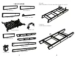
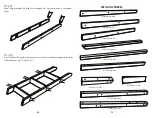
Page 14: ... 1 Tower Leg L04 2 Tower Leg L05 2 Wall Rail Board C09 2 Wall Rail Board C12 43 Step 61 Lay out and evenly space 7 Floorboards C14 as shown Attach the Floorboards using 84 Screws C2 Step 62 The following steps will guide you through the Ladder Assembly ...

Page 15: ...rden borders overhanging branches laundry lines and electrical wires Note Locate bare metal Platforms and Slides out of direct sunlight to reduce the likelihood of serious burns A Slide that faces north will receive the least direct sunlight Step 5 Maximum critical fall height for this Unit is 6ft 2m Place this Unit on level ground with protective surfacing applied to a depth that is suitable for ...

Page 16: ...t 3 Nuts A 2 into 1 Tower Leg L05 as shown Orient the Tower Leg as shown with the 7 large predrilled holes facing up 41 Step 57 Attach 1 Floorboard C17 to the Floor Supports C10 and H1 using 6 Screws C2 Step 58 Attach 1 Floorboard C16 to the Floor Supports C20 H1 and C10 using 4 Screws C2 90 90 ...

Page 17: ...rt 3 Nuts A 2 into 1 Tower Leg L05 as shown Orient the Tower Leg as shown with the 7 large predrilled holes facing up 40 Step 55 Attach 1 Floorboard 01 to the Baseboards C03 and C04 and the Floor Supports H1 and C20 using 6 Screws C2 Step 56 Lay out and evenly space 7 Floorboards C14 as shown Attach the Floorboards using 84 Screws C2 180 90 90 ...

Page 18: ...ct direction Ensure that the small pilot holes on the 2 Tower Legs L05 face the outside Step 12 Attach 1 Baseboard C04 to the Tower Legs using 6 Bolts A 2 39 Step 53 Attach 1 Floorboard C16 1 to the Floor Supports C10 using 4 Screws C2 Step 54 Attach 1 Floorboard C18 to the Baseboard C03 and Floor Supports H1 and C20 using 6 Screws C2 ...

Page 19: ...sure that the predrilled holes on the Rail Boards are closer to the Baseboard C04 Step 14 Stand the Tower Leg Assembly upright 38 Step 51 Attach 1 Floorboard C16 to the Floor Supports C10 using 4 Screws C2 Step 52 Attach 1 Floorboard C15 to the Floor Supports C10 and H1 using 6 Screws C2 ...

Page 20: ... are towards the top of the Baseboards Step 16 Insert 3 Nuts A 2 into 1 Tower Leg L02 as shown Orient the Tower Leg as shown with the 5 large predrilled holes facing up 37 Step 49 Attach 1 Floor Support H1 to the Baseboards C05 using 4 Screws C4 Ensure that the Floor Support is aligned with the top edge of the Baseboards Step 50 Attach 2 Floorboards C17 to the Floor Supports C10 and H1 using 12 Sc...

Page 21: ...hown Orient the Tower Leg as shown with the 4 small predrilled holes facing up Step 47 Attach 1 Floor Support H1 to the Baseboards C05 using 4 Screws C4 Ensure that the Floor Support is aligned with the top edge of the Baseboards Step 48 Attach 1 Floor Support H1 to the Baseboards C05 using 4 Screws C4 Ensure that the Floor Support is aligned with the top edge of the Baseboards 180 90 90 ...

Page 22: ...gs face the correct direction and that the 4 small predrilled holes on the Tower Legs are facing up Step 20 Attach 1 Floor Support C20 to the Tower Legs using 6 Bolts A 2 Step 45 Attach 1 Floor Support C10 to each Tower Leg C02 and Tower Leg C01 using 12 Screws C2 Step 46 Attach 1 Floor Support C10 to each Tower Leg L01 using 8 Screws C2 ...

Page 23: ... using 3 Nuts A3 and 3 Bolts A3 Step 22 Stand the Tower Leg Assembly upright Step 43 Attach 1 Floor Support C10 to each Tower Leg L05 and Tower Leg L04 using 12 Screws C2 Step 44 Attach 1 Floor Support C10 to Tower Legs L02 1 L03 and L02 using 12 Screws C2 ...

Page 24: ...rd and Floor Support are oriented as shown Step 24 Attach 1 Rail Board C08 to the Tower Legs L02 1 and L05 using 2 Nuts A1 and 2 Bolts A1 Step 41 Attach 1 Wall Rail Board C12 to Tower Legs L03 and L02 1 using 4 Screws B1 Step 42 Attach 1 Wall Rail Board C12 to Tower Legs L03 and L02 1 using 4 Screws B1 ...

Page 25: ...n Ensure the previously installed Nuts on the Tower Legs face the correct direction Step 39 Attach 1 Rail Board C07 to the Tower Legs using 3 Nuts A1 and 3 Bolts A1 Ensure the edges of the Rail board are flush with the edges of the Tower Legs Step 40 Attach 1 Wall Rail Board C09 to the Tower Legs L02 1 and L05 using 2 Screws B1 Ensure that the Wall Rail Board is aligned with the top edge of the Ra...

Page 26: ...the Tower Leg Assembly upright Step 37 Attach 1 Rail Board C07 to the Tower Legs using 3 Nuts A1 and 3 Bolts A1 Ensure the edges of the Rail board are flush with the edges of the Tower Legs Step 38 Attach 1 Wall Rail Board C09 to the Tower Legs L05 and L02 using 2 Screws B1 Ensure that the Wall Rail Board is aligned with the top edge of the Rail Board C13 ...

Page 27: ...using 1 Bolt A 2 Ensure the Floor Support is oriented as shown Step 30 Insert 3 Nuts A 2 into each Tower Leg L01 as shown Orient the Tower Legs as shown with the 2 large predrilled holes facing up Step 35 Secure the Baseboard C05 to the Tower Legs using 3 Bolts A 2 Step 36 Attach 2 Rail Boards C08 to the Tower Legs using 8 Nuts A1 and 8 Bolts A1 ...

Page 28: ...ep 32 Stand the Tower Leg Assembly upright Step 33 Attach the Tower Leg Assembly to the Rail Board C08 using 1 Nut A1 and 1 Bolt A1 Attach the Tower Leg Assembly to the Baseboard C05 using 1 Bolt A 2 Step 34 Attach 1 Rail Board C08 to the Tower Legs using 4 Nuts A1 and 4 Bolts A1 ...

Reviews: