1.5
Optional Accessories
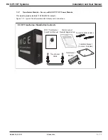
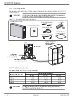
Optional Accessories describes the options available for upgrades and enhancement of the EX 5/7/11 RT systems.
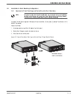
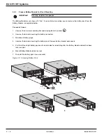
Detailed installation of the unit is described in following sections.
To ensure a successful installation, all procedures should be followed in their correct sequence. Note that any
unauthorized installation may cause damage to the UPS(s) and void the MGE Office Protection Systems warranty.
1.5.1
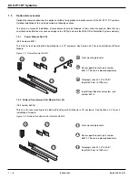
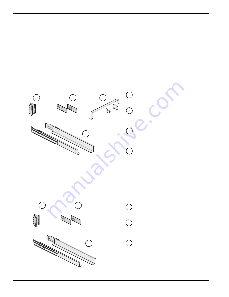
Power Module Rail Kit
(Part Number 86001)
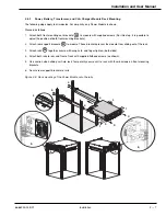
This kit is for rack mounting the Power Module in a 19" enclosure. See Section 2.4.3 for rack installation of Power
Module.
Figure 1-7: Power Module Rail Kit.
Front mounting brackets.
Rear support brackets, part number
86013. This can be ordered separately.
Telescopic rails, 25.16" to 39.61"
length (639 mm to 1005 mm).
Input/Output Box bracket system, part
number 86012.
1.5.2 Battery/Transformer/CLA Module Rail Kit
(Part number 86002)
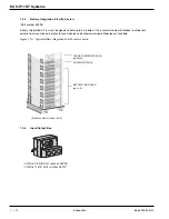
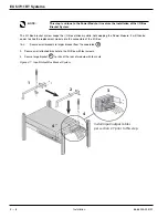
This kit is for rack mounting of the Battery/Transformer/CLA Module in 19" enclosure. See Section 2.4.3 for rack
installation of module.
Figure 1-8: Battery/Transformer/CLA Module Rail Kit.
Front mounting brackets.
Rear support brackets, part number
86013. This can be ordered separately.
Telescopic rails, 25.16" to 39.61"
length (639 mm to 1005 mm).
26
25
24
27
26
25
24
EX 5/7/11 RT Systems
Introduction
1 — 8
86-86000-00 B01
26
24
25
27
24
25
26
Summary of Contents for 11+
Page 1: ...w w w m g e o p s c o m EX 5 7 11 RT Systems Installation and User Manual ...
Page 2: ......
Page 4: ... This page left blank intentionally EX 5 7 11 RT Systems iv 86 86000 00 B01 ...
Page 14: ... This page left blank intentionally EX 5 7 11 RT Systems c x 86 86000 00 B01 ...
Page 46: ... This page left blank intentionally EX 5 7 11 RT Systems 2 20 86 86000 00 B01 ...
Page 62: ... This page left blank intentionally EX 5 7 11 RT Systems 4 6 86 86000 00 B01 ...
Page 68: ......
Page 72: ...EX 5 7 11 RT Systems G 4 86 86000 00 B01 This page left blank intentionally ...
Page 74: ......
Page 75: ......


