Installation and User Manual
2.4.3
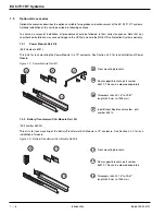
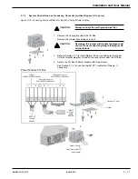
Power, Battery, Transformer, and CLA Charger Module Rack Mounting
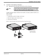
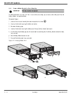
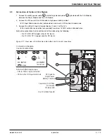
The following steps apply to all modules. For simplicity, only Power Module is shown.
Proceed as follows:
1.
Attach both front mounting ear brackets
to module with supplied screws. (For this step, it is possible to
adjust the position of both front mounting brackets.)
2.
Attach rear support brackets
to module. These brackets prevent the module from sliding out of the rack.
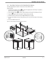
3.
Attach rails
together, secure with wing nuts, and finger tighten. (both sides).
4.
Attach both rails to rear and front of rack with supplied flathead screws (as shown).
5.
Use caution when sliding unit into rack. Temporarily secure unit to rack with thumb screws on front mounting
brackets.
6.
Secure rear support brackets to rails.
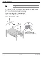
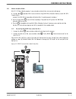
Figure 2-6: Rack mounting of the Power Module onto the rails.
26
25
24
Installation
2 — 7
86-86000-00 B01
3
4
4
4
4
2
2
1
4
4
5
1
6
6
6
6
Summary of Contents for 11+
Page 1: ...w w w m g e o p s c o m EX 5 7 11 RT Systems Installation and User Manual ...
Page 2: ......
Page 4: ... This page left blank intentionally EX 5 7 11 RT Systems iv 86 86000 00 B01 ...
Page 14: ... This page left blank intentionally EX 5 7 11 RT Systems c x 86 86000 00 B01 ...
Page 46: ... This page left blank intentionally EX 5 7 11 RT Systems 2 20 86 86000 00 B01 ...
Page 62: ... This page left blank intentionally EX 5 7 11 RT Systems 4 6 86 86000 00 B01 ...
Page 68: ......
Page 72: ...EX 5 7 11 RT Systems G 4 86 86000 00 B01 This page left blank intentionally ...
Page 74: ......
Page 75: ......

