background image

3.3

Make sure wires are secured properly.

3.4

Refit and secure the terminal block cover.

3.5

Battery-module connections

3.5.1

Comet EXtreme 4,5 and 6 kVA

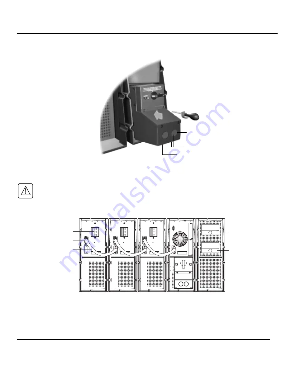
3.5.1.1  Check that the battery circuit breaker is OFF.

3.5.1.2  Connect cable to the connectors of the electronic and battery modules.

Input

Battery CB

Battery Cable Connector

Battery Cable

BATTERY #3

BATTERY #2

BATTERY #1

UPS

TRANSFORMER

Output

10

86-153721-01

Comet EXtreme Transformer Distribution Cabinet

output (front feed or bottom feed)

power connection knock-outs

input (front feed or bottom feed)

Summary of Contents for 12 kVA

Page 1: ...Comet EXtreme 4 5 6 9 12 kVA Start Up Guide...

Page 2: ...ation Items included in 4 5 6 kVA tower configuration battery module electronics module transformer optional battery module electronics module transformer optional battery module NOTE Connection and o...

Page 3: ...See Figure 1 2 3 Remove terminal block cover 3 on I O Box 2 4 Remove cable entry knockouts 4 at rear of I O Box 2 5 Insert cables for input power left and output power right thru knockouts Be sure cab...

Page 4: ...to the INPUT terminal block L1 L2 L1 L2 INPUT OUTPUT L1 L2 L3 INPUT OUTPUT 120 104 N 104 120 208 VAC FROM UTILITY TO LOAD 208 VAC I O BOX TO LOAD 120 VAC 208VAC 240VAC OR TO OPTIONAL POWER DISTRIBUTI...

Page 5: ...FROM UTILITY 4 5 6 KVA ISO TRANSFORMER 240 VAC INPUT L1 L2 L3 NEUT OUTPUT 104A 104B 120A 120B GND 208 240 208 VAC 240 VAC L1 INPUT OUTPUT 4 5 6 KVA UPS L2 L1 L2 208 VAC INPUT FROM UTILITY 4 5 6 KVA IS...

Page 6: ...CK LAYOUT NOTE UPS AND ISOLATION TRANSFORMER ARE FACTORY CONFIGURED AT 208 VAC 208 VAC FROM UTILITY I O BOX TO LOAD 208 VAC TO LOAD 120 VAC 208VAC 240VAC OR TO OPTIONAL POWER DISTRIBUTION MODULE PDM O...

Page 7: ...figured with software 9 12 KVA XFMR SCHEMATIC 208 VAC INPUT H1 H2 OUTPUT AT 208 VAC TRANSFORMER INPUT L1 X7 X6 X1 X5 L2 104 120 GND N 104 120 104 120 GND N 104 120 X4 X3 X2 NOT USED IN 208 VAC APPLICA...

Page 8: ...L1 L2 L3 INPUT OUTPUT 120 104 N 104 120 TO LOAD 120 VAC 208VAC 240VAC OR TO OPTIONAL POWER DISTRIBUTION MODULE PMM L1 L2 L3 INPUT OUTPUT 120 104 N 104 120 TO LOAD 120 VAC 208VAC 240VAC OR TO OPTIONAL...

Page 9: ...B 120A 120B GND 208 240 4 5 6 KVA ISO TRANSFORMER 240 VAC INPUT L1 L2 L3 NEUT 104A 104B 120A 120B GND 208 240 240 VAC INPUT OUTPUT OUTPUT L1 INPUT OUTPUT 9 12 KVA UPS L2 L1 L2 208 VAC INPUT FROM UTILI...

Page 10: ...battery circuit breaker is OFF 3 5 1 2 Connect cable to the connectors of the electronic and battery modules Input Battery CB Battery Cable Connector Battery Cable BATTERY 3 BATTERY 2 BATTERY 1 UPS T...

Page 11: ...rmation 4 1 Battery Scan Test This procedure is a test for each battery to verify it is in basic working order To verify it holds a charge batteries should be charged for several hours before testing...

Page 12: ...s in the ON position 4 1 10 After approximately 30 seconds at least one of the four yellow LEDs on the front panel of the UPS should be lit Additionally the Battery Input LED 20 on the front panel of...

Page 13: ...tected equipment one load at a time If the UPS beeps an alarm when you start your equipment the UPS may be overloaded 4 2 4 The four LEDs on the right side of the front of the UPS show the percent of...

Page 14: ...w w w m g e u p s c o m 1660 Scenic Avenue Costa Mesa California 92626 714 557 1636...

Reviews: